Wireless communications system and wireless communication device
a wireless communication and wireless communication technology, applied in the field of wireless communication devices and wireless communication systems, can solve the problems of increasing the amount of traffic in the wireless communication band to the point of hindering communication, increasing the burden on the host unit, and insufficient channel switching in some cases, so as to reduce the interruption of communication, prevent the increase of extra processing and extra traffic involved, and improve the efficiency of the use of multiple bands
- Summary
- Abstract
- Description
- Claims
- Application Information
AI Technical Summary
Benefits of technology
Problems solved by technology
Method used
Image
Examples
first embodiment
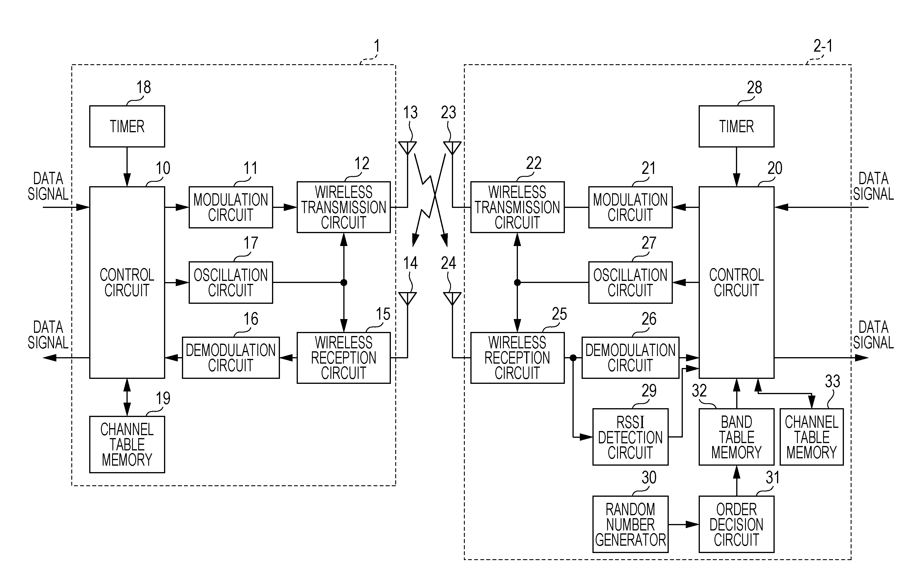
[0031]In the first embodiment, a single host unit equipped with a wireless communication device performs wireless communication with at least one remote unit each equipped with a wireless communication device. The host unit may be a controller for monitoring cameras, for example, and the remote units may be monitoring cameras, for example. FIG. 1 is a block diagram illustrating the configuration of the wireless communications system according to the first embodiment. The wireless communications system includes a wireless communication device 1 of a single host unit, and a wireless communication device 2-1 of at least one remote unit. The wireless communication device 1 is an example of a first wireless communication device, and the wireless communication device 2-1 is an example of a second wireless communication device. The following description supposes that N remote units are present, where N is an integer equal to or greater than 2. The wireless communication devices 2-2 to 2-N ...
second embodiment
[0073]The wireless communications system according to a second embodiment has the same structure as or similar structure to that of the wireless communications system in the first embodiment except that wireless communication devices 2a-1 to 2a-N are included in remote units in place of the wireless communication devices 2-1 to 2-N. The wireless communication devices 2a-1 to 2a-N of the remote units have identical or similar configurations to each other. FIG. 13 is a block diagram illustrating the configuration of the wireless communication device 2a-1 in the wireless communications system according to the second embodiment. The wireless communication device 2a-1 includes a control circuit 20, a modulation circuit 21, a wireless transmission circuit 22, a transmit antenna 23, a receive antenna 24, a wireless reception circuit 25a, a demodulation circuit 26, an oscillation circuit 27, a timer 28, an RSSI detection circuit 29, a random number generator 30a, an order decision circuit 3...
third embodiment
[0079]The wireless communications system according to a third embodiment has the same structure as or similar structure to that of the wireless communications system in the first embodiment except that wireless communication devices 2b-1 to 2b-N are included in remote units in place of the wireless communication devices 2-1 to 2-N. The wireless communication devices 2b-1 to 2b-N of the remote units have identical or similar configurations to each other. FIG. 14 is a block diagram illustrating the configuration of the wireless communication device 2b-1 in the wireless communications system according to the third embodiment. The wireless communication device 2b-1 includes a control circuit 20, a modulation circuit 21, a wireless transmission circuit 22, a transmit antenna 23, a receive antenna 24, a wireless reception circuit 25b, a demodulation circuit 26, an oscillation circuit 27, timer 28, an RSSI detection circuit 29, a random number generator 30b, an order decision circuit 31, a...
PUM
 Abstract
Description
Claims
Application Information
 - R&D
- Intellectual Property
- Life Sciences
- Materials
- Tech Scout
- Unparalleled Data Quality
- Higher Quality Content
- 60% Fewer Hallucinations
Browse by: Latest US Patents, China's latest patents, Technical Efficacy Thesaurus, Application Domain, Technology Topic, Popular Technical Reports.
© 2025 PatSnap. All rights reserved.Legal|Privacy policy|Modern Slavery Act Transparency Statement|Sitemap|About US| Contact US: help@patsnap.com


