Measuring apparatus for the filling level of a container

a technology of measuring apparatus and container, which is applied in the direction of liquid/fluent solid measurement, instruments, machines/engines, etc., can solve the problems of inability to feed the measurement arm through to the opposite side of the housing, the play or tolerance of the measurement arm bearing can be undesirably increased, and the displacement limitation and frictional force between the bearing and the measuremen

Inactive Publication Date: 2016-06-23
ROBERT BOSCH GMBH
View PDF1 Cites 9 Cited by
  • Summary
  • Abstract
  • Description
  • Claims
  • Application Information

AI Technical Summary

Benefits of technology

[0030]According to one embodiment of the invention, the connecting piece comprises a plastic. One advantage can be seen in that owing to malleability during the manufacture of such a connecting piece, an advantageous adaptation of the structures of the connecting piece to the measurement arm and / or the magnet element is possible. Furthermore, diverse forms of the connecting piece can be implemented in a comparatively simple way depending on the circumstances of the housing, of the magnet element and of the magnetically sensitive element.
[0031]In one example, the magnetically sensitive element is a Hall effect sensor. With such a sensor, the so-called Hall effect is used for the measurement of magnetic fields. According to this principle, an output voltage is produced by the sensor that is for example proportional to the product of the magnetic field strength of the magnet element and a current through the sensor.

Problems solved by technology

Said non-axial arrangement of the magnet element and the magnetically sensitive element can result in a compromise regarding the accuracy and linearity of the measurement results depending on a filling level.
Feeding the measurement arm through to an opposite side of the housing is not possible with such end of shaft magnet elements.
By using only one bearing, a play or tolerance of a measurement arm bearing can be undesirably increased with time owing to the friction and forces that occur.
In particular, with bearings made of plastic an increase of the bearing area can result in displacement limitations and frictional forces between the bearing and the measurement arm.
Furthermore, leverage forces can occur owing to the comparatively small supporting surfaces on the housing, and said leverage forces can result in expansion of the bearing and resulting additional room to move for the measurement arm and hence measurement inaccuracies.

Method used


Image

  • Measuring apparatus for the filling level of a container
  • Measuring apparatus for the filling level of a container
  • Measuring apparatus for the filling level of a container

Examples


Embodiment Construction

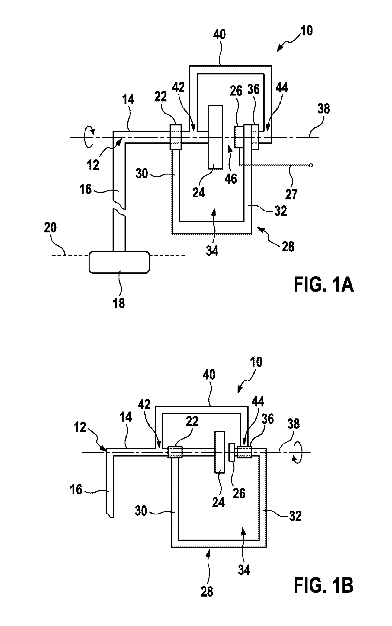
[0040]FIG. 1A shows a measuring apparatus 10 for measurement of a filling level of a liquid surface 20, for example in a container, in a simplified way. The measuring apparatus 10 comprises a measurement arm 12 with a first region 14 and a second region 16. The second region 16 of the measurement arm 12 protrudes towards the liquid surface 20 in this case. For this purpose, for example a float element 18 can be mounted on the remote end of the second region 16 of the measurement arm 12, which produces a coupling between the level of the liquid surface 20 and a deflection movement of the second region 16 of the measurement arm 12. In the event of a change of the liquid surface 20, a displacement of the float element 18 is produced that triggers an angular displacement of the second region 16 of the measurement arm 12. The first region 14 of the measurement arm encloses an angle, for example of 90°, with the second region 16 of the measurement arm 12 in this case. In this way, a rotar...


PUM


Abstract

The invention relates to a measuring apparatus (10) for measuring a filling level of a container, which measuring apparatus has a measuring arm (12) with a float element (18) which is designed to change its angular position about a rotation axis (38) depending on the filling level. A magnet element (24) is connected to one end of the measuring arm (12) in a rotationally fixed manner. A magnet-sensitive element (26) is designed to output a measurement signal (27) depending on the angular position of the magnet element (24). The measuring apparatus (10) is characterized in that the measuring arm (12) is mounted in a first bearing (22) and additionally in a second bearing (36), wherein the magnet element (24) is arranged in an intermediate space (34) between the first bearing (22) and the second bearing (36).

Description

BACKGROUND OF THE INVENTION[0001]The present invention concerns the measurement of a filling level in a container. In particular, the invention concerns a measuring apparatus for measurement of a filling level based on a magnetic measurement principle.[0002]Level measuring devices are used in many different technological areas. In particular, in vehicle technology measurement apparatuses can be used that measure different liquid levels, such as of fuel, cooling liquid, brake fluid or similar for example. Accurate measurement of filling levels with small measurement tolerances can be necessary for the safe operation and reliability of a vehicle. For the technical implementation, a number of different requirements can be placed on such measurement apparatuses at the same time. For example, besides robustness and durability, as well as a resistance to different chemical compounds, high accuracy of the measurement results may be required.[0003]Thus for example, measurement sensors are k...

Claims


Application Information

Patent Timeline
Patent Type & Authority Applications(United States)
IPC IPC(8): G01F23/38
CPCG01F23/38G01F23/32
Inventor TESAR, PETRKALAS, MARTINNEKULA, JAN
Owner ROBERT BOSCH GMBH
Why Eureka
Try Eureka