
Wind turbine rotor blades with support flanges

Inactive Publication Date: 2016-06-23
GENERAL ELECTRIC CO
View PDF7 Cites 3 Cited by
  • Summary
  • Abstract
  • Description
  • Claims
  • Application Information

AI Technical Summary

Benefits of technology

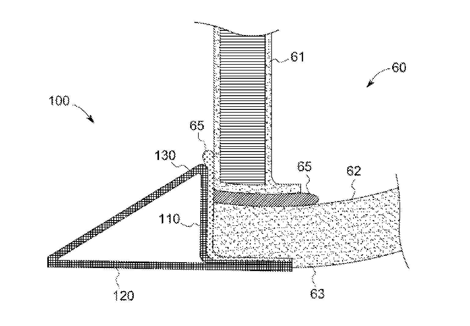
The patent describes wind turbine rotor blades that have a structural support member and an airfoil structure. The airfoil structure is supported by the structural support member and includes a shell portion and one or more load-transferring exterior panels. The blade also has a support flange that connects the airfoil structure to the structural support member. The patent offers different configurations for the support flange, including a connection wall that extends between the first and second walls. The patent aims to provide improved structural integrity and aerodynamic performance of wind turbine rotor blades.

Problems solved by technology

However, the weight of the rotor blade may become a factor as its size continues to increase.
While multiple different extensions, features or other variants may be utilized to alter the aerodynamic profile of a rotor blade, each of these additional components may also contribute to the overall weight of the rotor blade.

Method used


Image

  • Wind turbine rotor blades with support flanges
  • Wind turbine rotor blades with support flanges
  • Wind turbine rotor blades with support flanges

Examples


Embodiment Construction

[0017]One or more specific embodiments of the present invention will be described below. In an effort to provide a concise description of these embodiments, all features of an actual implementation may not be described in the specification. It should be appreciated that in the development of any such actual implementation, as in any engineering or design project, numerous implementation-specific decisions must be made to achieve the developers' specific goals, such as compliance with system-related and business-related constraints, which may vary from one implementation to another. Moreover, it should be appreciated that such a development effort might be complex and time consuming, but would nevertheless be a routine undertaking of design, fabrication, and manufacture for those of ordinary skill having the benefit of this disclosure.

[0018]When introducing elements of various embodiments of the present invention, the articles “a,”“an,”“the,” and “said” are intended to mean that ther...


PUM


Abstract

Rotor blades for wind turbines include a structural support member disposed internal the rotor blade that extends for at least a portion of a rotor blade span length, an airfoil structure supported by the structural support member, and a support flange connecting the airfoil structure to the structural support member. The support flange includes a first wall connected to the structural support member, a second wall connected to the airfoil structure, and a connection wall that extends between the first wall and the second wall.

Description

STATEMENT REGARDING FEDERALLY SPONSORED RESEARCH & DEVELOPMENT[0001]This invention was partially made with government support under government contract No. DE-AR0000293 awarded by the Department of Energy. The government has certain rights to this invention.BACKGROUND OF THE INVENTION[0002]The subject matter disclosed herein relates to wind turbine rotor blades and, more specifically, to wind turbine rotor blades with load transferring exterior panels.[0003]Wind power is considered one of the cleanest, most environmentally friendly energy sources presently available, and wind turbines have gained increased attention in this regard. A modern wind turbine typically includes a tower, generator, gearbox, nacelle, and one or more rotor blades connected to a hub either directly or through a pitch bearing. The rotor blades capture kinetic energy of wind using known airfoil principles. The rotor blades transmit the kinetic energy in the form of rotational energy so as to turn a shaft coupli...

Claims


Application Information

Patent Timeline
IPC IPC(8): F03D1/06
CPCF03D1/0675Y02E10/72F05D2240/30F05D2250/61
Inventor CARUSO, CHRISTOPHER DANIELYARBROUGH, AARON ALPHEUS
Owner GENERAL ELECTRIC CO
Learn More