
Hierarchical Control of Micro-grids

a micro-grid and hierarchy technology, applied in the direction of dc source parallel operation, transportation and packaging, ac network load balancing, etc., can solve the problems of increasing the power characteristics of such micro-grids, difficult control, and little or no inertia of the grid, and achieve simple control system and high speed

Active Publication Date: 2016-06-02
OSLSOFT INC
View PDF5 Cites 15 Cited by
  • Summary
  • Abstract
  • Description
  • Claims
  • Application Information

AI Technical Summary

Benefits of technology

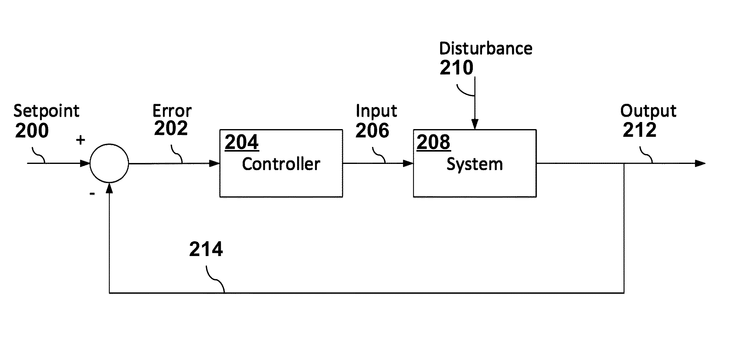
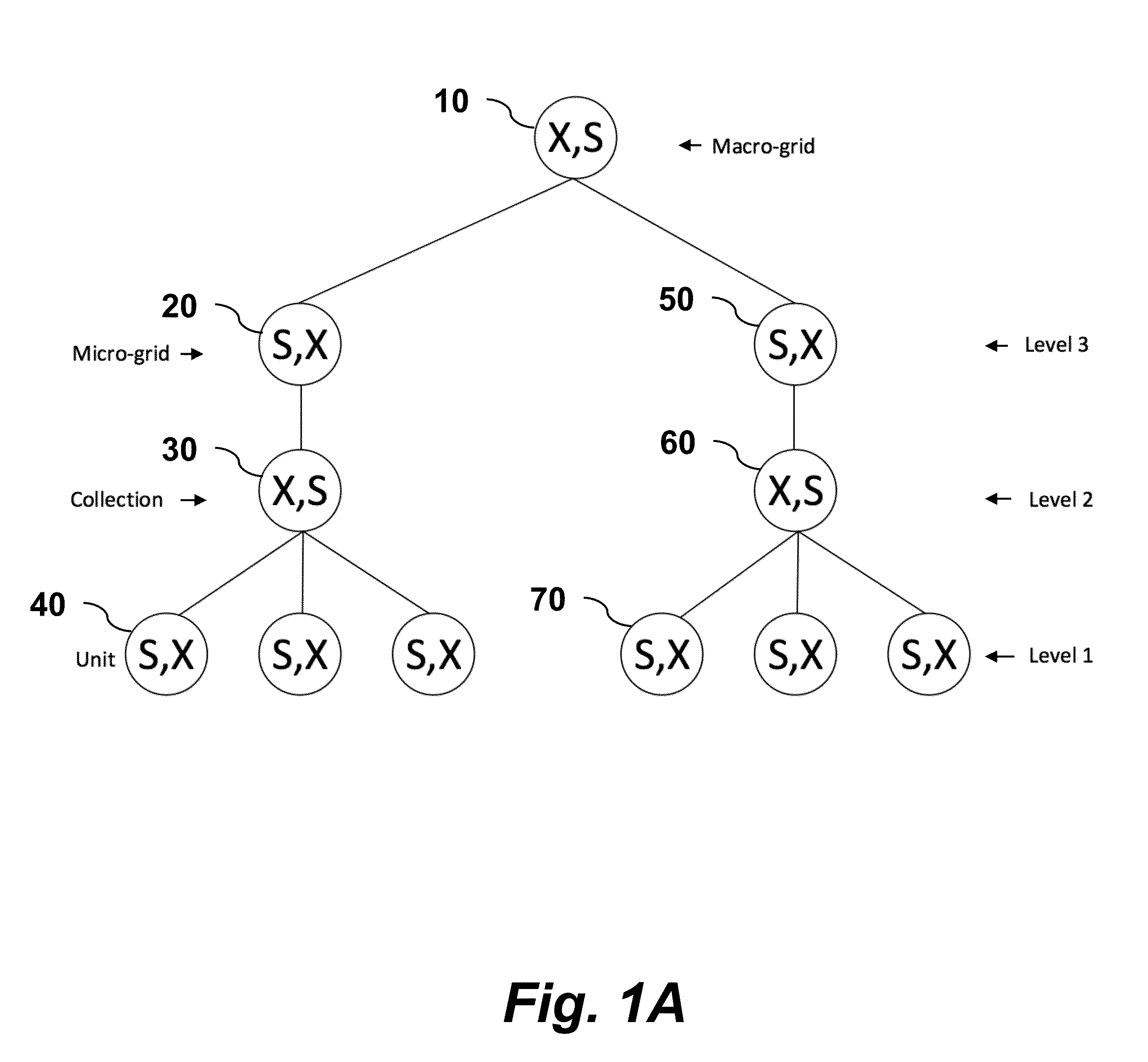
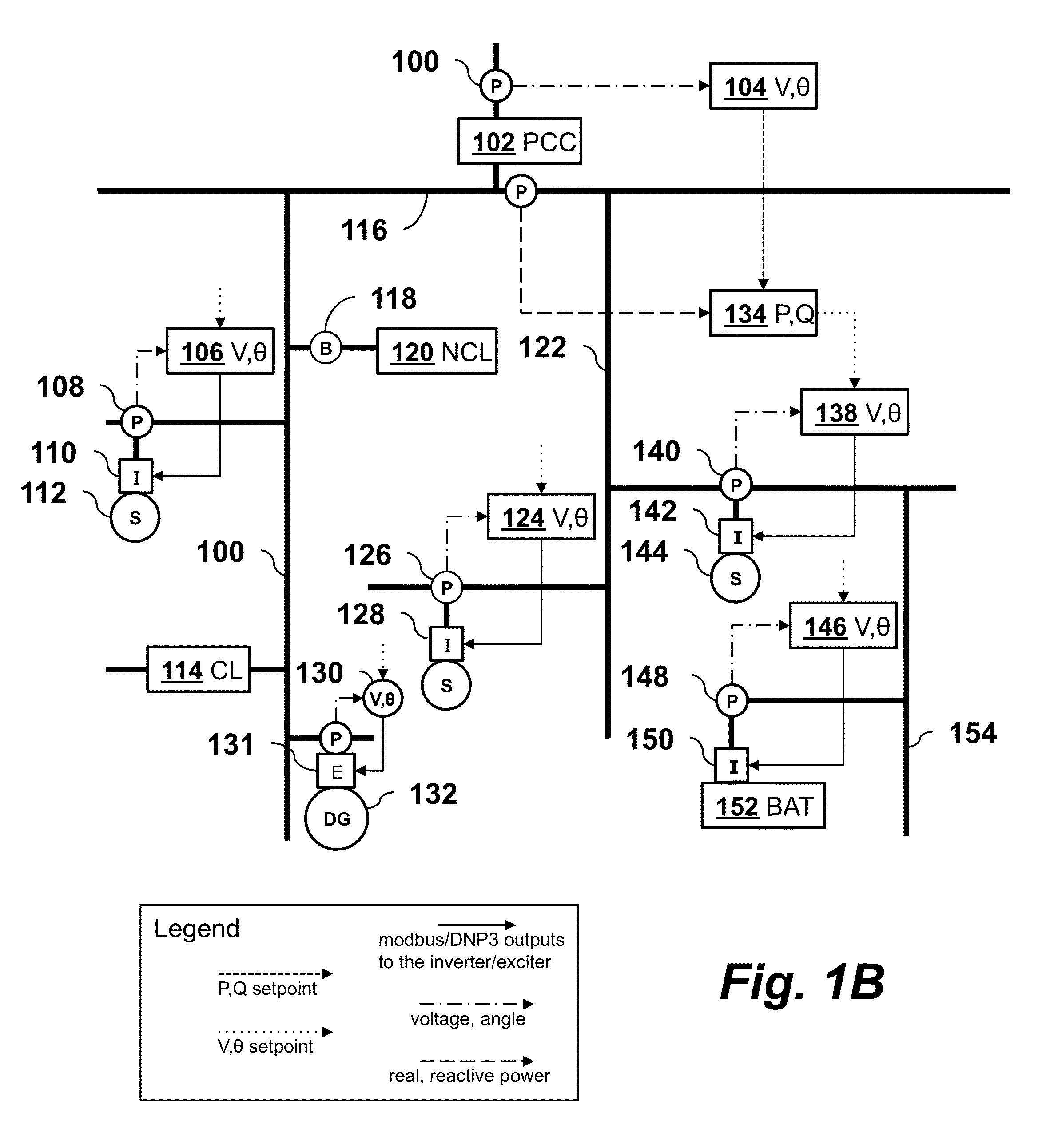
The present invention is about using a hierarchical decoupled controller for controlling micro-grids. The controllers use real time feedback control to regulate voltage, frequency, and angle, or real and reactive power. The controllers are fast and simple compared to other systems. The invention provides a micro-grid control system using a first and second 2x2 decoupled controller that work together to control the voltage and angle, or real and reactive power. This system is efficient and effective in controlling micro-grids. The control system can also include a third 2x2 decoupled controller that supervises the setpoints of the second controller. The voltage and angle, or real and reactive power, are time synchronized with a GPS clock.

Problems solved by technology

The renewable energy resources (Solar PV, fuel cell, battery, wind) in a micro-grid have little or no inertia and hence are difficult to control compared to systems with high inertia from rotating energy sources like combustion turbines or conventional steam turbines powered by conventional fossil fuels such as coal or natural gas.
Controlling the power characteristics of such micro-grids is an increasing problem, since variations in frequency or voltage can cause the micro-grid to be disconnected from the broader macro-grid.

Method used


Image

  • Hierarchical Control of Micro-grids
  • Hierarchical Control of Micro-grids
  • Hierarchical Control of Micro-grids

Examples


Embodiment Construction

Nomenclature

[0018]PMU—phasor measurement unit.

CAISO—California Independent System Operator.

[0019]S—Apparent power (a vector of real and reactive power).

P—real power, watts.

Q—reactive power, vars.

V—voltage, volts.

δ—unwrapped angle, degrees.

X—vector of voltage angle and voltage, used in “State” estimation.

State—sufficient information about any system such that future states can be computed given measurements of the inputs.

Unit—a DER with P, and Q output that generally can be specified, typical in “smart” inverters.

DER—distributed energy resources, examples, include Photovoltaic Inverter based systems, fuel cells, wind power, CHP such as combined cycle gas turbine or micro generator, fuel cells and batteries.

Macro-grid—the main grid to which the micro-grid is attached.

Micro-grid—a collection of loads and sources, that act as a single point of control to the macro-grid and can disconnect and re-connect to the macro-grid.

StateVariables—the pair of voltage and voltage angle at a point in ...


PUM


Abstract

A micro-grid control system has a first 2×2 decoupled controller that controls voltage and voltage angle by adjusting real and reactive power using real time feedback, and a second 2×2 decoupled controller that controls real and reactive power by adjusting voltage and voltage angle using real time feedback. The first 2×2 decoupled controller and second 2×2 decoupled controller together form a hierarchical microgrid control system, where the second 2×2 decoupled controller is a supervisory controller of the first 2×2 decoupled controller. The micro-grid control system may also include a third 2×2 decoupled controller that supervises the second 2×2 controller.

Description

CROSS-REFERENCE TO RELATED APPLICATIONS[0001]This application claims priority from U.S. Provisional Patent Application 62 / 086,479 filed Dec. 2, 2014, which is incorporated herein by reference.FIELD OF THE INVENTION[0002]The invention relates to electrical power grids and, more specifically, to methods and systems for monitoring and controlling such power grids.BACKGROUND OF THE INVENTION[0003]Renewable energy power sources, such as solar photovoltaic (PV) arrays and wind turbines, are connected into micro-grids that are part of an area Electric Power System (macro-grid). In the near future, an estimated 25% of renewable resources will be behind utility and customer owned micro-grids at 50% total renewable generation and thus will be a significant portion of the future electric power grid. There will be many participants with control of the renewable sources with little knowledge of the complex grid and how it is managed. Micro-grids are a collection of loads and generation sources t...

Claims


Application Information

Patent Timeline
Patent Type & Authority Applications(United States)
IPC IPC(8): H02J3/38
CPCH02J3/382H02J3/16H02J3/32H02J2310/10H02J2300/10H02J2300/20H02J2300/24H02J3/381Y02E10/56Y02E40/30H02J3/388H02J3/40
Inventor WELLS, CHARLES H.
Owner OSLSOFT INC
Learn More