
Microstrip antenna structure and microwave imaging system using the same

a microstrip antenna and imaging system technology, applied in the field of microstrip antenna structure and microwave imaging system using the same, can solve the problems of reducing detection accuracy, reducing the detection accuracy, and reducing the resolution and quality of scan images, so as to improve the image resolution and quality of objects, improve the electrical length of the ring microstrip line, and reduce the return loss

Inactive Publication Date: 2016-05-26
METAL INDS RES & DEV CENT
View PDF8 Cites 6 Cited by
  • Summary
  • Abstract
  • Description
  • Claims
  • Application Information

AI Technical Summary

Benefits of technology

The technical effect of this patent is to provide a microstrip antenna structure that uses a short coupling gap structure for better performance at frequencies above 5 GHz. This results in improved electrical length and strength, as well as multiple resonances and reduced return loss. The invention also includes a microwave imaging system with this microstrip antenna structure, which improves image resolution and quality.

Problems solved by technology

However, the known microstrip antenna is easily affected by conductor loss and dielectric loss of the substrate, such that excessive return losses may be encountered at a high-frequency operating environment, resulting in performance degradation of the radio communication device.
However, because the microwave imaging system is usually operated in a high-frequency environment, if the known microstrip antenna is applied in the microwave imaging system, the resolution and quality of scan images may be degraded due to excessive return loss of the known microstrip antenna at high frequency, leading to lower the detection accuracy.

Method used


Image

  • Microstrip antenna structure and microwave imaging system using the same
  • Microstrip antenna structure and microwave imaging system using the same
  • Microstrip antenna structure and microwave imaging system using the same

Examples


Embodiment Construction

[0039]In the following description, the disclosure will be explained with reference to embodiments thereof. However, these embodiments are not intended to limit the disclosure to any specific environment, applications or particular implementations described in these embodiments. Therefore, the description of these embodiments is only for the purpose of illustration rather than to limit the disclosure. In the following embodiments and attached drawings, elements not directly related to the disclosure are omitted from depiction; and the dimensional relationships among individual elements in the attached drawings are illustrated only for ease of understanding, but not to limit the actual scale.

[0040]It will be understood that, although the terms “first” and “second” may be used herein to describe various elements, components, regions, layers and / or sections, these elements, components, regions, layers and / or sections should not be limited by these terms. These terms are only used to di...


PUM


Abstract

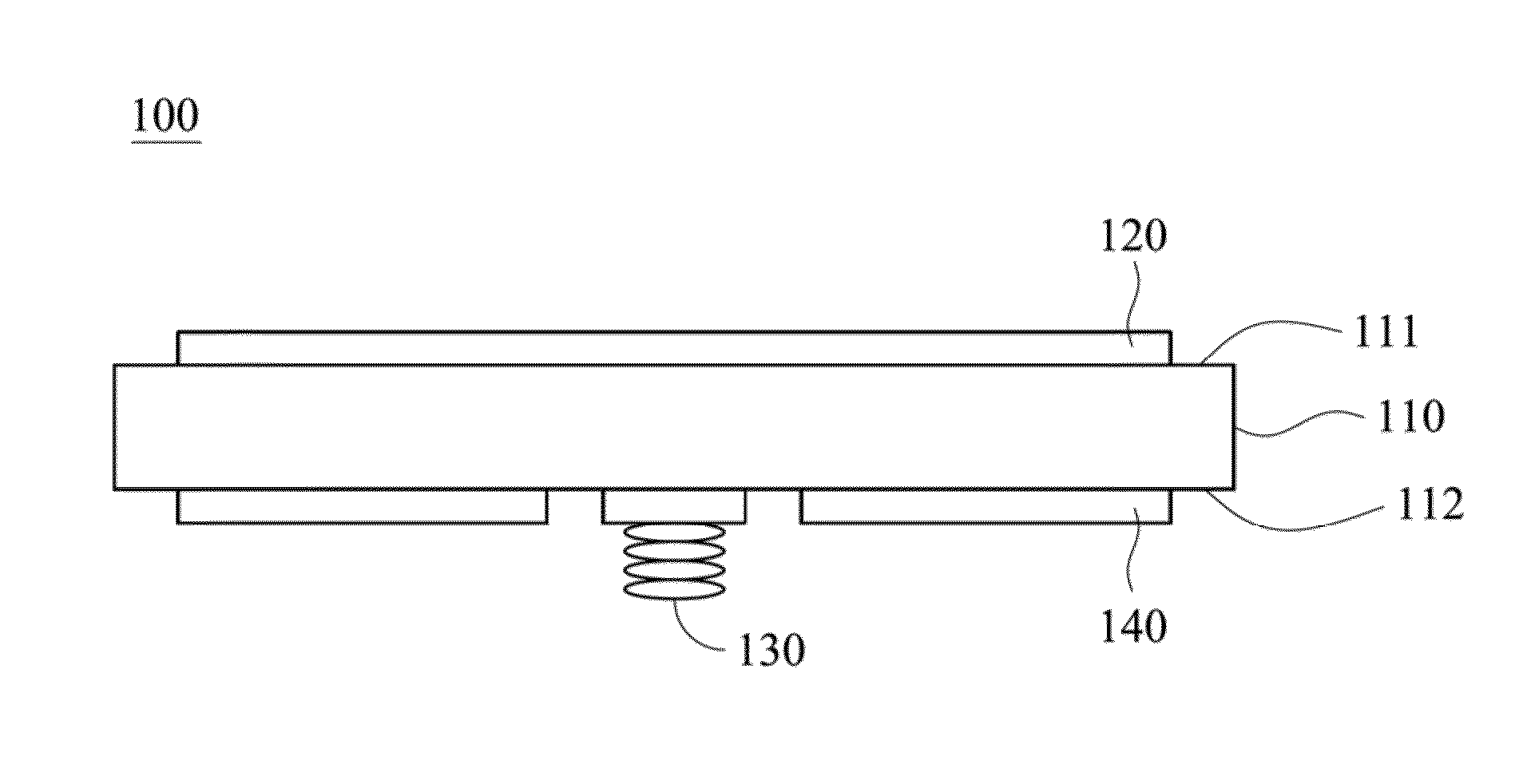
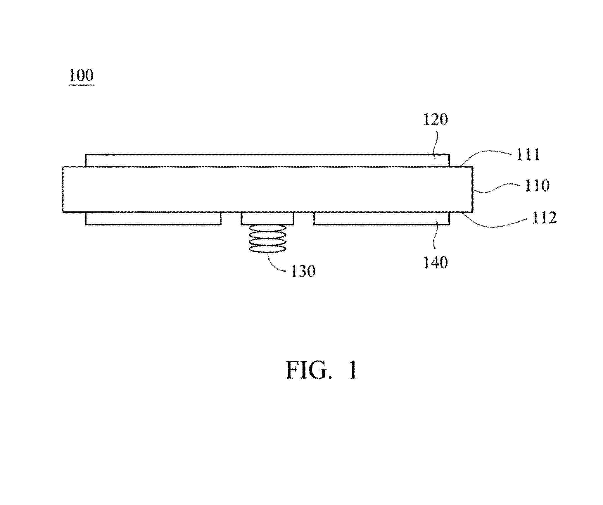
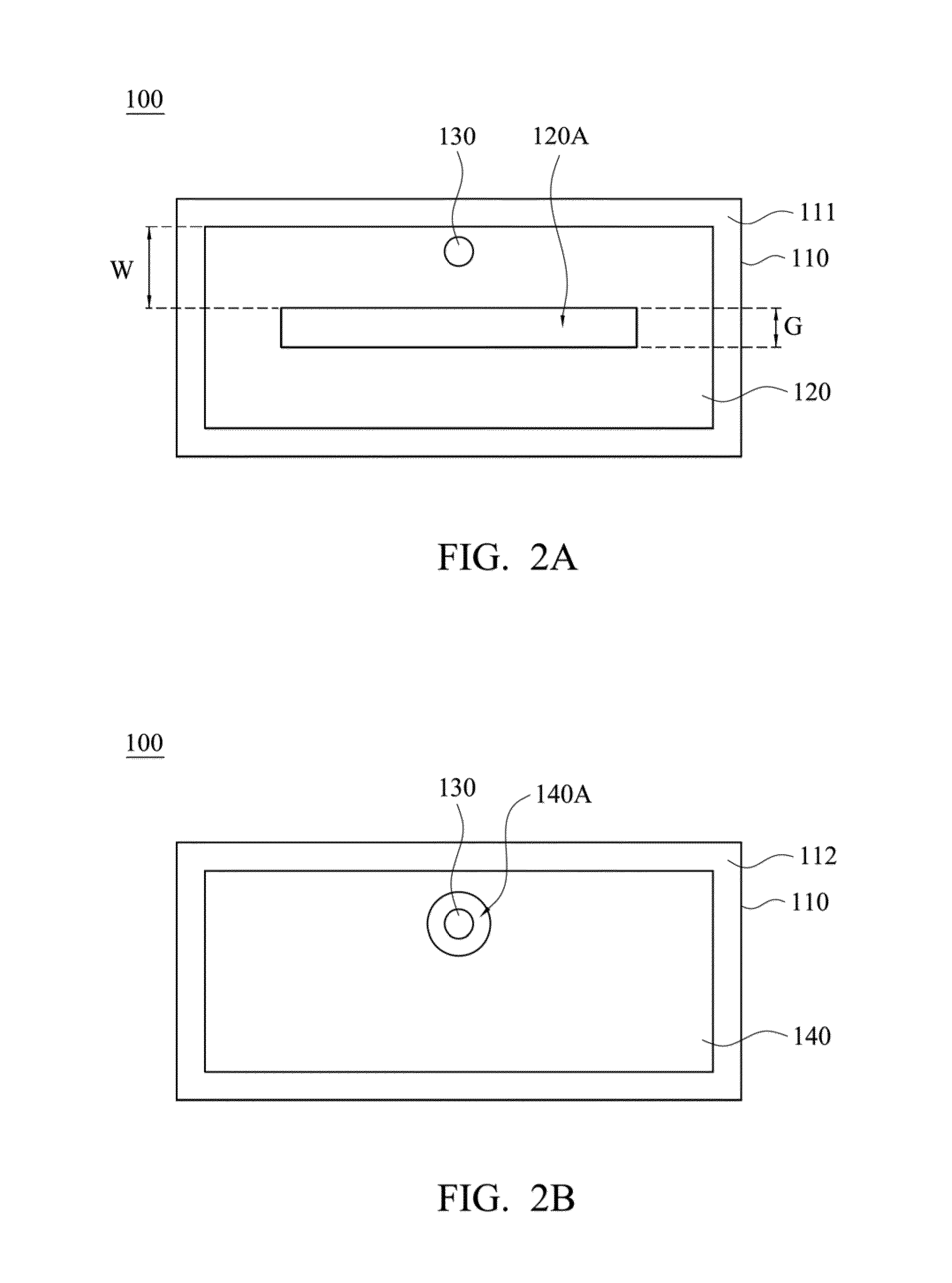
A microstrip antenna structure is provided, which includes a substrate, a ring microstrip line and a signal transmission port. The substrate has opposite first and second surfaces. The ring microstrip line is disposed on the first surface of the substrate. The ring microstrip line has a short coupling gap ranged between 0.004λg and 0.06λg for forming a radiation bandwidth with high selectivity, where λg represents a guided wavelength of an electromagnetic wave in the ring microstrip line corresponding to a center frequency of the radiation bandwidth. The signal transmission port is disposed on the second surface of the substrate. The signal transmission port penetrates through the substrate and is electrically connected to the ring microstrip line.

Description

RELATED APPLICATIONS[0001]This application claims priority to Taiwan Application Serial Number 103140845, filed on Nov. 25, 2014, which is herein incorporated by reference.BACKGROUND[0002]1. Field of Disclosure[0003]The invention relates to a microstrip antenna structure and a microwave imaging system using the same, and more particularly, to microstrip antenna structure that can improve performance when operated in a high-frequency environment and a microwave imaging system using the same.[0004]2. Description of Related Art[0005]Microstrip antennas have the advantages such as light weight, small size and easy to manufacture and therefore, has been widely applied to radio communication devices such as mobile phones, navigators that demand of lightening and thinning. For the microstrip antennas, the generated radiation pattern, gain and polarity mainly depend on the structure and shape of the microstrip antenna. However, the known microstrip antenna is easily affected by conductor lo...

Claims


Application Information

Patent Timeline
IPC IPC(8): H01Q9/04A61B5/05
CPCA61B5/0507H01Q9/0407A61B2562/0228H01Q9/0442H01Q21/065H01Q21/08H01Q9/045
Inventor HUNG, CHENG-YUANWENG, MIN-HANGLAN, SIANG-WENCHANG, SHOOU-JINNYANG, RU-YUANYU, TSUNG-CHIH
Owner METAL INDS RES & DEV CENT
Learn More