
Method for measuring bearing cup gap in universal joint and method for manufacturing universal joint to which the measuring method is applied

Active Publication Date: 2016-05-26
JTEKT CORP
View PDF3 Cites 2 Cited by
  • Summary
  • Abstract
  • Description
  • Claims
  • Application Information

AI Technical Summary

Benefits of technology

The present invention provides a method for measuring the gap between the bottom surfaces of bearing cups and the joint spider member in a universal joint. This method uses elastic bending and compressive deformation data on the arms and the joint spider member to accurately and easily determine the gap. Overall, this measuring method enables the bearing cups to be easily assembled to the joint spider member and manufactured with accuracy.

Problems solved by technology

Therefore, when the press fitting load is released, the arms may be sprung back by a distance corresponding to the applied press fitting load, the shape and rigidity of each arm, and the like, resulting in a difference in size between gaps (bearing cup gaps) formed in the first bearing cup and in the second bearing cup.

Method used


Image

  • Method for measuring bearing cup gap in universal joint and method for manufacturing universal joint to which the measuring method is applied
  • Method for measuring bearing cup gap in universal joint and method for manufacturing universal joint to which the measuring method is applied
  • Method for measuring bearing cup gap in universal joint and method for manufacturing universal joint to which the measuring method is applied

Examples


Embodiment Construction

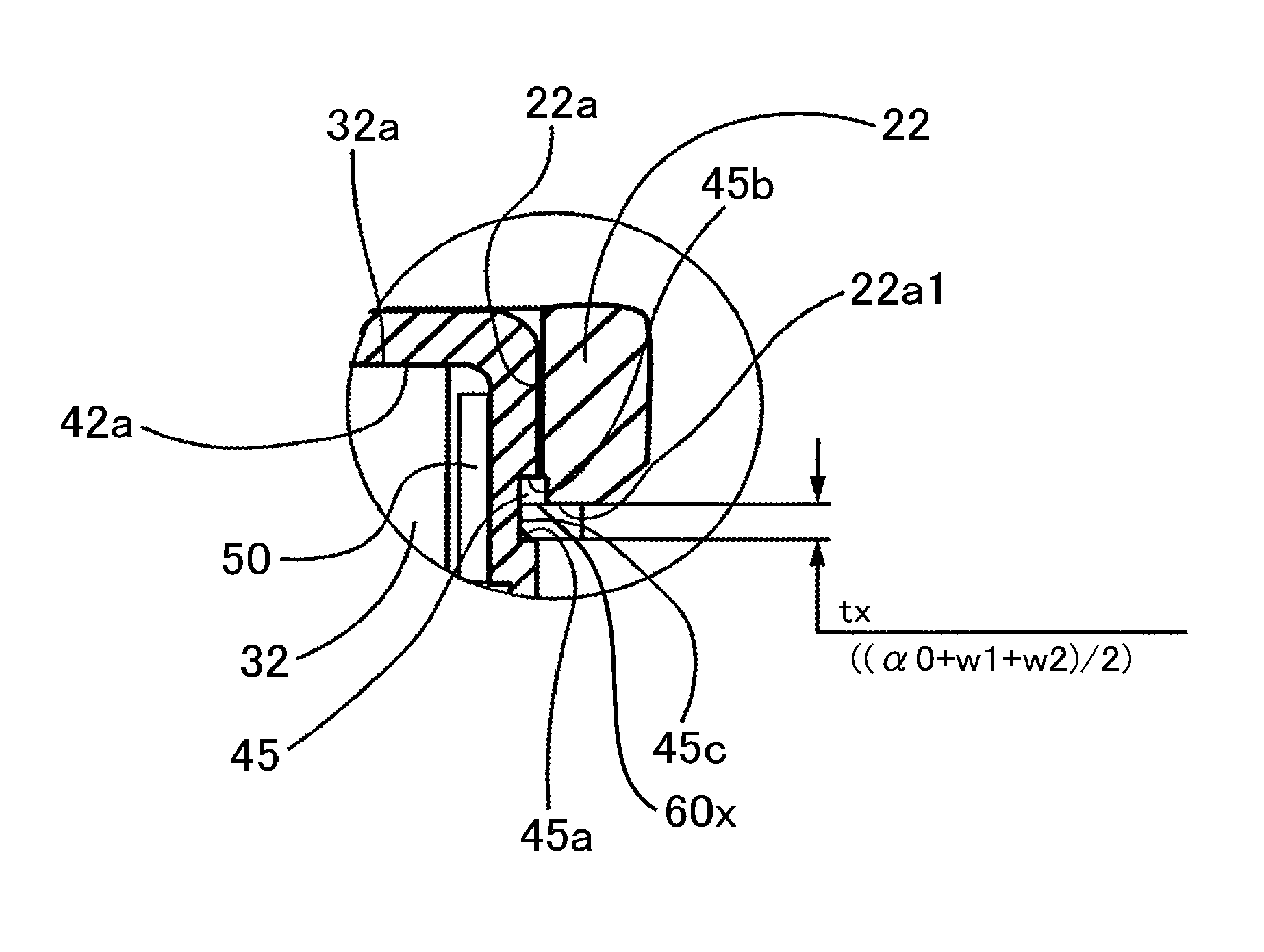
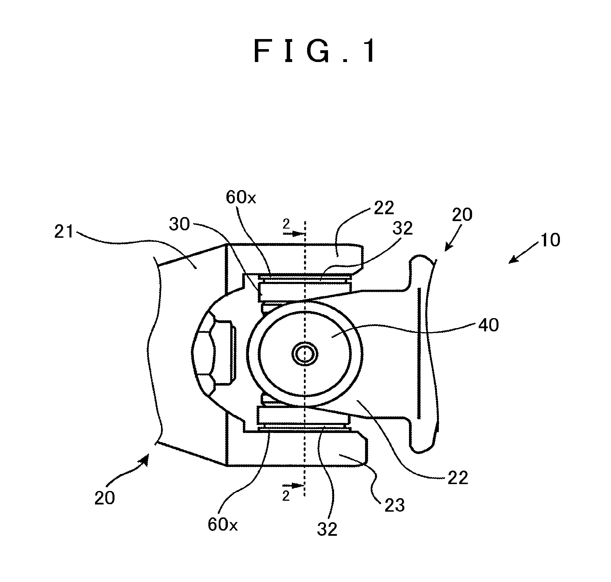
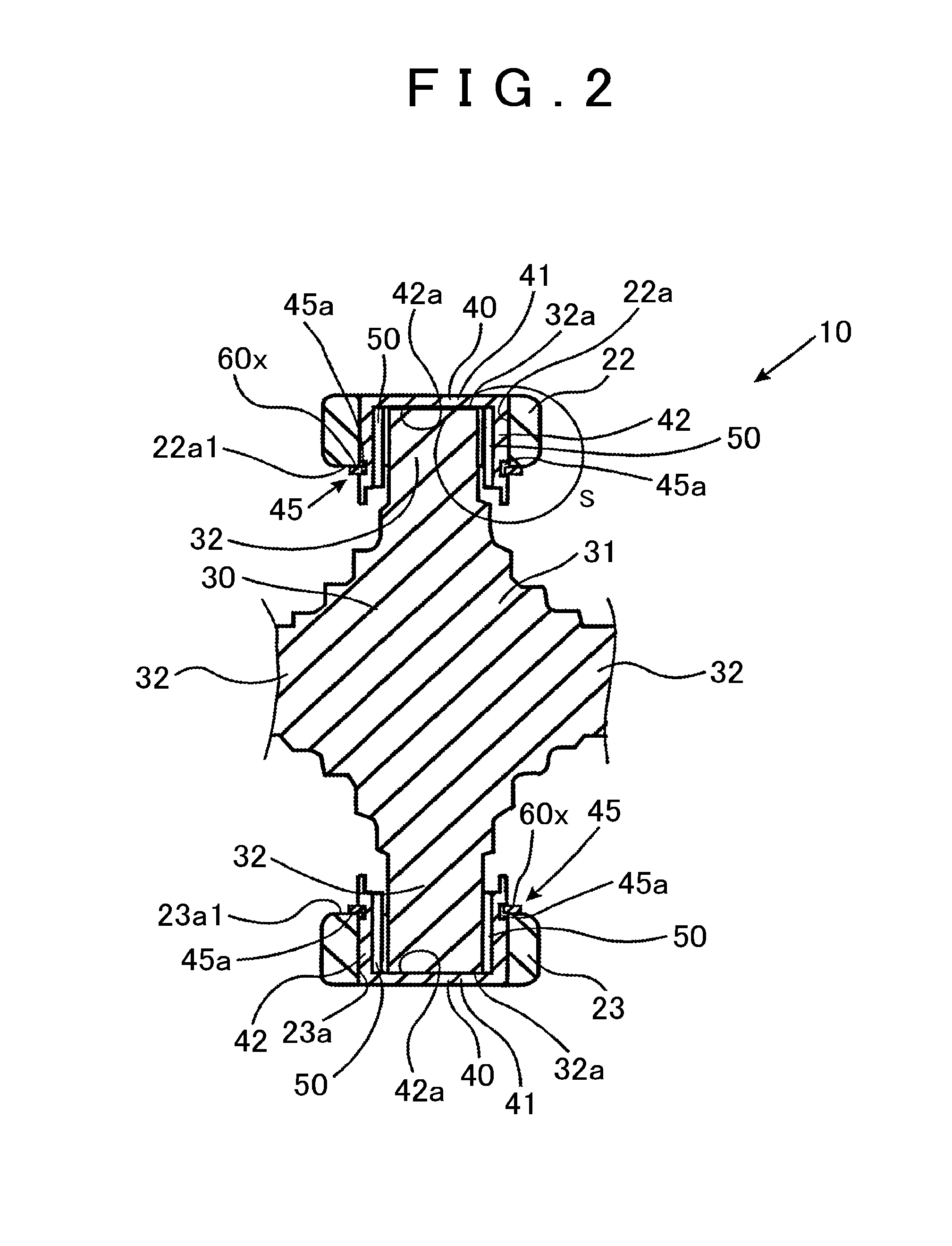
[0029]A method for measuring a bearing cup gap and a method for manufacturing a universal joint to which the measuring method is applied according to an embodiment of the present invention will be described below with reference to the drawings. First, with reference to FIG. 1 and FIG. 2, a universal joint 10 (also referred to as a cross joint) to be assembled according to the present invention will be described.

[0030]As depicted in FIG. 1 and FIG. 2, the universal joint 10 includes yoke members 20, a joint spider member 30, bearing cups 40, needle bearings 50, and snap rings 60x (see FIG. 3). Of two sets of combinations each of the bearing cups and the joint spider member, only the combination of the bearing cups 40 and the joint spider member 30 depicted in a section in FIG. 2 will be described below.

[0031]As depicted in FIG. 1 and FIG. 2, the yoke member 20 includes a yoke main body portion 21 secured to a tip of a drive shaft (not depicted in the drawings) and a pair of arms 22 a...


PUM


Abstract

Provided are a method for measuring a bearing cup gap in a universal joint that enables bearing cups to be easily and accurately assembled to a yoke member, and a manufacturing method for a universal joint, to which the measuring method is applied. The measuring method is used for a universal joint including a yoke member, bearing cups, and a joint spider member to measure gaps between bottom surfaces of the bearing cups and the joint spider member. The method includes acquiring first relationship data, acquiring second relationship data, acquiring a displacement amount of the pair of bearing cups, and calculating a gap between bottom surfaces of the bearing cups and end surfaces of a pair of shaft portions based on the first relationship data, the second relationship data, and the displacement amount.

Description

INCORPORATION BY REFERENCE[0001]The disclosure of Japanese Patent Application No. 2014-237864 filed on Nov. 25, 2014 including the specification, drawings and abstract, is incorporated herein by reference in its entirety.BACKGROUND OF THE INVENTION[0002]1. Field of the Invention[0003]The present invention relates to a measuring method for a bearing cup gap in a universal joint installed in, for example, a vehicle, and a method for manufacturing a universal joint to which the measuring method is applied.[0004]2. Description of Related Art[0005]For example, as a universal joint used for a drive shaft, a steering apparatus, or the like in a vehicle, a universal joint described in Japanese Patent Application Publication No. H7-233820 (JP H7-233820 A) is known. The universal joint described in JP H7-233820 A includes: a joint spider member 12 with four shafts 12a (shaft portions) arranged in the shape of a cross; and bottomed tube-like bearing cups 14 installed so as to be rotatable rela...

Claims


Application Information

Patent Timeline
IPC IPC(8): F16D3/38G01B5/14G01B5/30F16D3/40
CPCF16D3/385G01B5/30G01B5/14F16D3/40F16D3/382F16D2300/12F16C35/067F16D3/41F16C21/005
Inventor YAMAISHI, HIROAKI
Owner JTEKT CORP
Learn More