
System and methods for with a first and a second hand operated control, controlling motion on a work tool for a construction machine

a technology of construction machinery and control means, which is applied in the direction of mechanical machines/dredgers, analogue processes for specific applications, instruments, etc., can solve the problems of affecting the productivity of the driver, and affecting the work efficiency of the driver, so as to achieve more intuitive control

Active Publication Date: 2016-05-26
STEELWRIST AB
View PDF4 Cites 7 Cited by
  • Summary
  • Abstract
  • Description
  • Claims
  • Application Information

AI Technical Summary

Benefits of technology

This patent presents a system and method for controlling the movement of a work tool on a construction machine with greater intuitiveness. The system allows for adjustment of the velocity of the movement based on the desired task. The attachment device allows for both rotation and tilting of the tool. The system includes first and second control means that can move the tool in a parallel movement and rotate about a perpendicular axis. Overall, the system provides greater control and efficiency for construction machines and their tools.

Problems solved by technology

These three movements must be made simultaneously and in such a way that none of the three valves opens too much or too little, which would mean that it becomes an “unbalanced movement”.
This is not a natural and intuitive way of working, and makes the drivers productivity lower and the learning curve longer than it would need to be.
This gives yet another control parameter to be handled simultaneously, which complicates the work of the driver.
Without a free hanging unit, the crane risks being subjected to such large torque caused by the falling tree that the machine may break.
Since the work tool, when employing crane tip controlling on forest machinery, is hanging loosely, there is no way of controlling the exact location, rotation and position of the tool relative to the tip of the crane.

Method used


Image

  • System and methods for with a first and a second hand operated control, controlling motion on a work tool for a construction machine
  • System and methods for with a first and a second hand operated control, controlling motion on a work tool for a construction machine
  • System and methods for with a first and a second hand operated control, controlling motion on a work tool for a construction machine

Examples


Embodiment Construction

[0037]In the following there is a detailed description of embodiments of the invention. All examples shall be seen as parts of the general description and is therefore generally possible to combine.

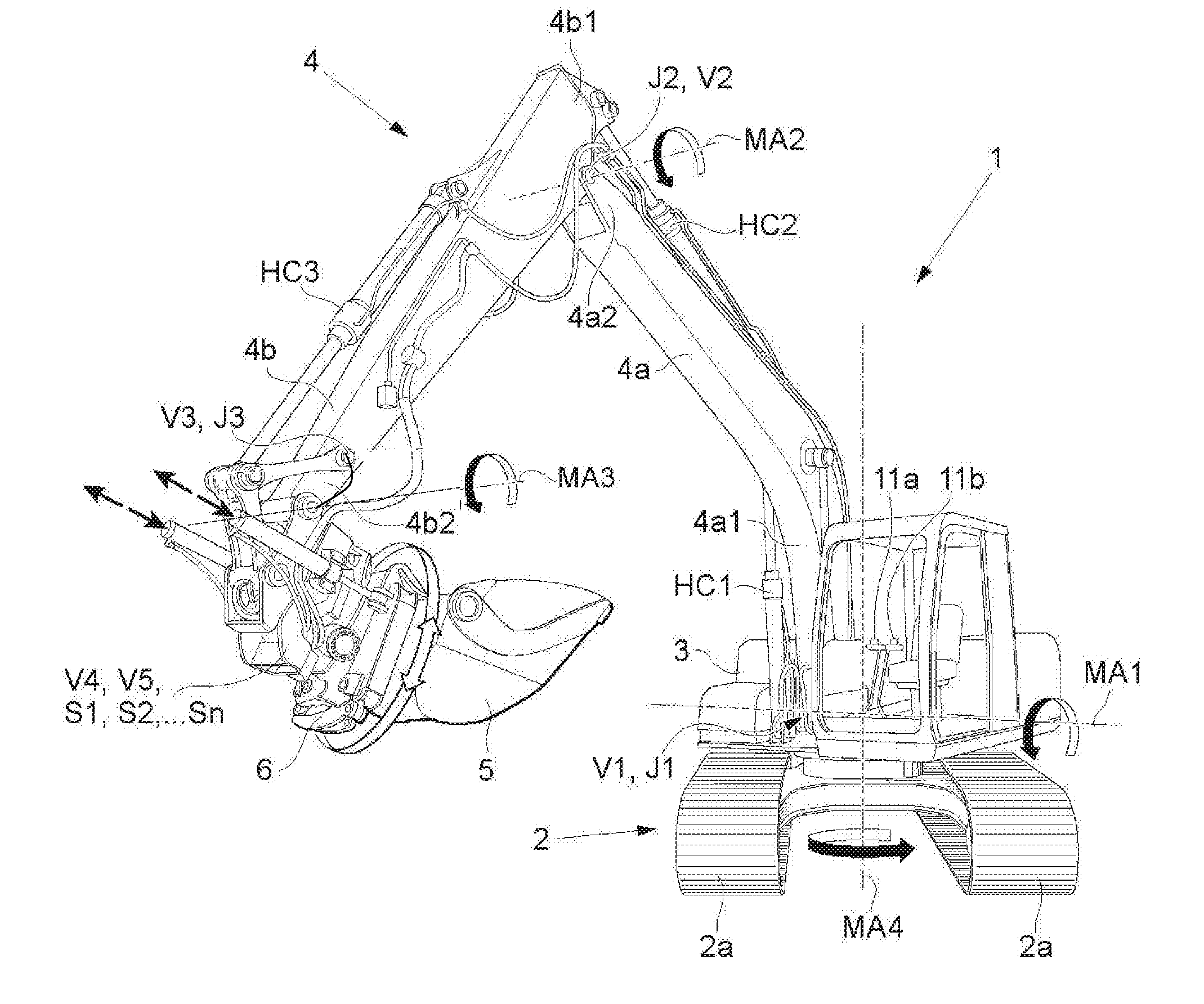
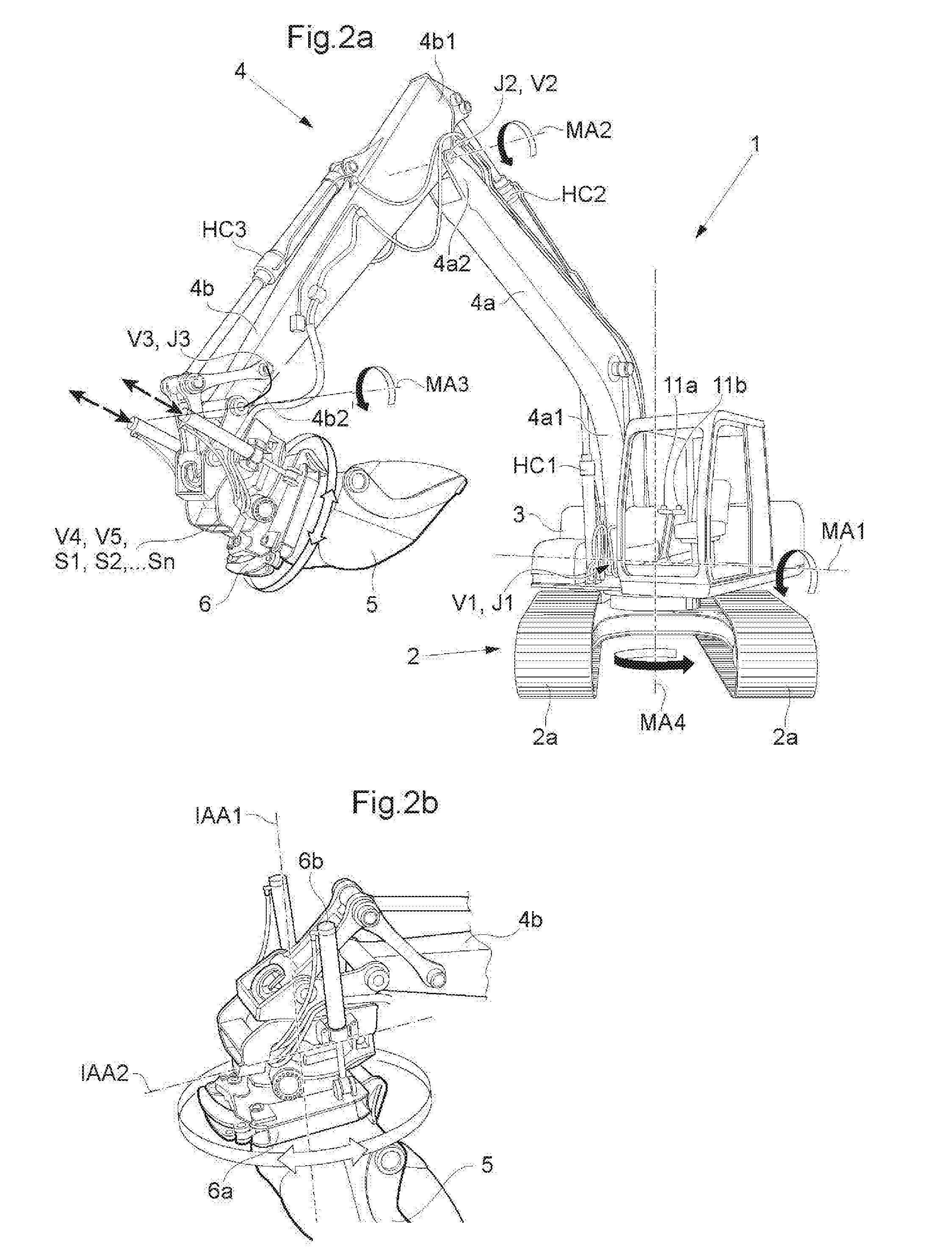
[0038]In FIG. 2a there is shown a construction machine 1 for which the system is suitable. The construction machine 1 comprises preferably a bottom carriage 2 with a driving belt 2a, a top 3 as well as a digging arm 4 and a work tool 5. The driving belts 2a are of course replaceable with wheels if desired. The digging arm 4 is made up of a at least one inner 4a and one outer link arm 4b, boom and shaft respectively, where the digging arm is made up of an inner link arm 4a with a first and a second inner link arm end 4a1, 4a2 and an outer link arm 4b with a first and a second outer link arm end 4b1, 4b2. One joint J1 connects the top 3 with the first inner link arm end 4a1 and one joint J2 connects the second inner link arm end 4a2 with the first outer link arm end 4b1. In the outer link a...


PUM


Abstract

The invention relates to a system and a method for, with a first and a second hand operated control means (11a, 11b), controlling movement on a work tool (5) for a construction machine (1). The construction machine (1) comprises a lower carriage (2), a top (3), a digging arm (4) and a work tool (5). The digging arm (4) comprises an inner link arm (4a) with a first and a second inner link arm end (4a1, 4a2) and an outer link arm (4b) with a first and a second outer link arm end (4b1, 4b2). The work tool (5) is secured in the second outer link arm end (4b2) via an attachment device (6) which enables controlled rotation and controlled tilting of the work tool (5) in relation to the outer link arm (4b). The system is characterized in that the first hand operated control means (11a) is intended to control the position of the second outer link arm end (4b2) and the second hand operated control means (11b) is intended to control the function of the tool (5), comprising controlled rotation and controlled tilting of the work tool (5) in relation to the outer link arm (4b).

Description

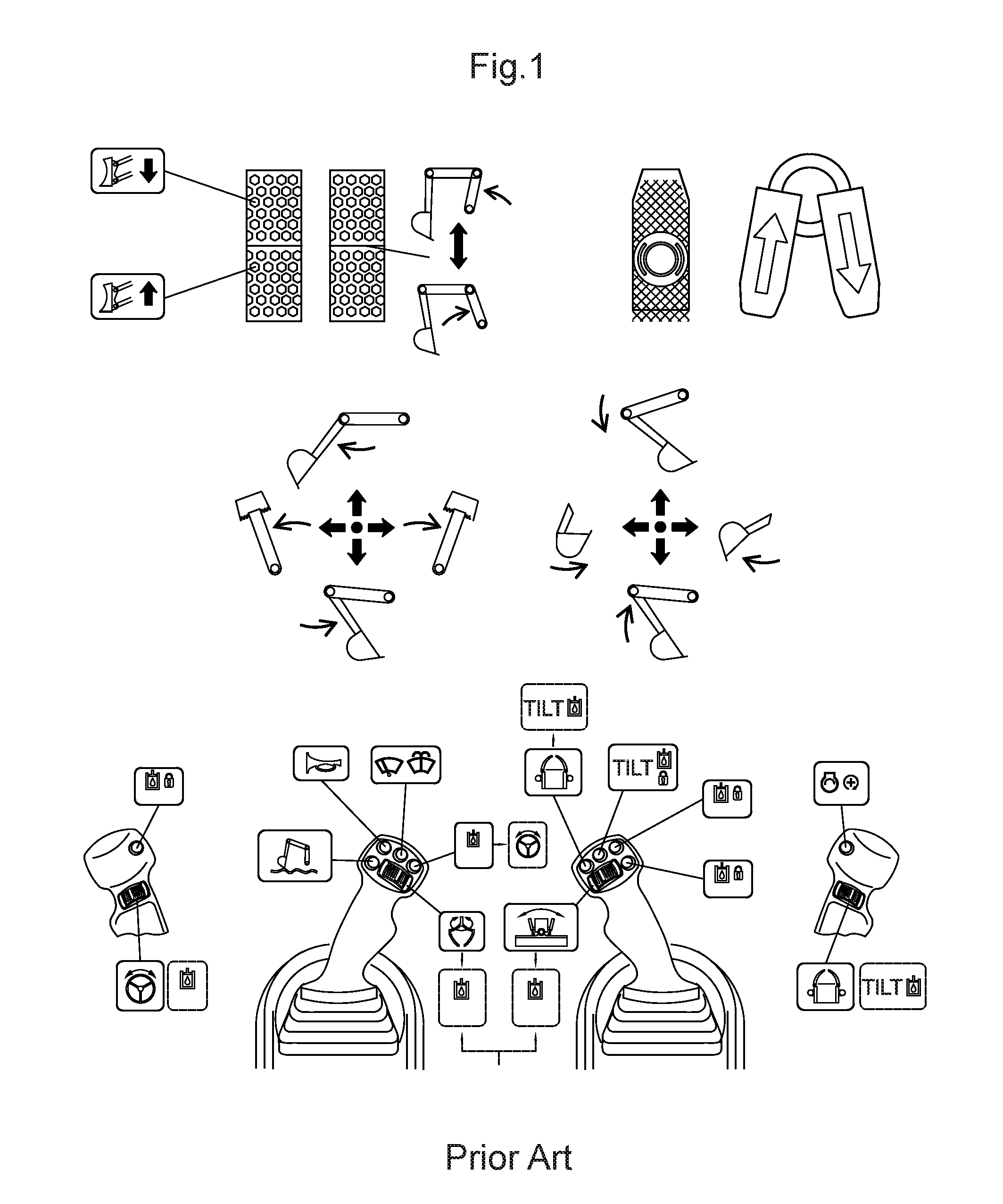
TECHNICAL FIELD[0001]The present invention relates to a system and a method for, with a first and a second hand operated control means, controlling movement on a work tool for a construction machine.BACKGROUND[0002]The digging performed with a construction machine is performed with an excavation unit made from two fixed link arms, boom and shaft respectively, as well as a work tool in the form of e.g. a bucket. Until the start of the 1960's, excavation units were maneuvered with steel wires and winches that would pull up the bucket, so called [bucket wheels].[0003]Today, construction machines such as excavators, are controlled via joysticks in such a way that every input in a joystick controls a specific hydraulic valve. Each hydraulic valve then controls a certain cylinder or engine, which in turn controls the movement in a certain direction on the arm of the excavator (see FIG. 1), as the previous machines were controlled with wires and winches. In order to perform a specific oper...

Claims


Application Information

Patent Timeline
Patent Type & Authority Applications(United States)
IPC IPC(8): E02F9/20E02F3/32E02F3/43
CPCE02F9/2004E02F3/32E02F3/435E02F3/3677E02F3/3681E02F3/437E02F9/265
Inventor STOCKHAUS, STEFANNILSSON, MARKUS
Owner STEELWRIST AB
Learn More