
Self clocking comparator for a charge pump

a self-clocking comparator and charge pump technology, applied in pulse automatic control, pulse technique, multi-input and output pulse circuits, etc., can solve the problems of delay in time before the comparator output does, in fact, change, control loop to unstable or nearly unstable,

Active Publication Date: 2016-05-19
SILICON LAB INC
View PDF3 Cites 14 Cited by
  • Summary
  • Abstract
  • Description
  • Claims
  • Application Information

AI Technical Summary

Benefits of technology

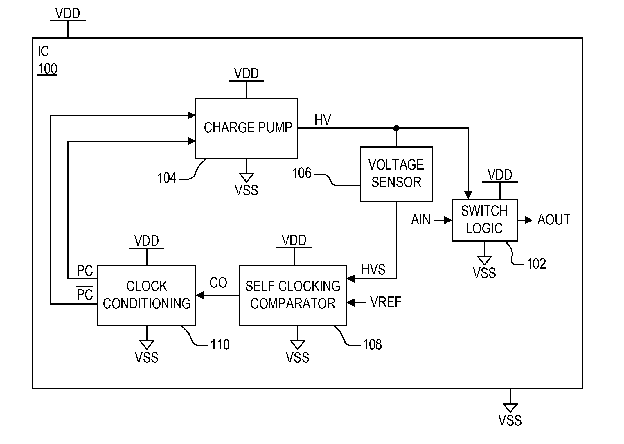
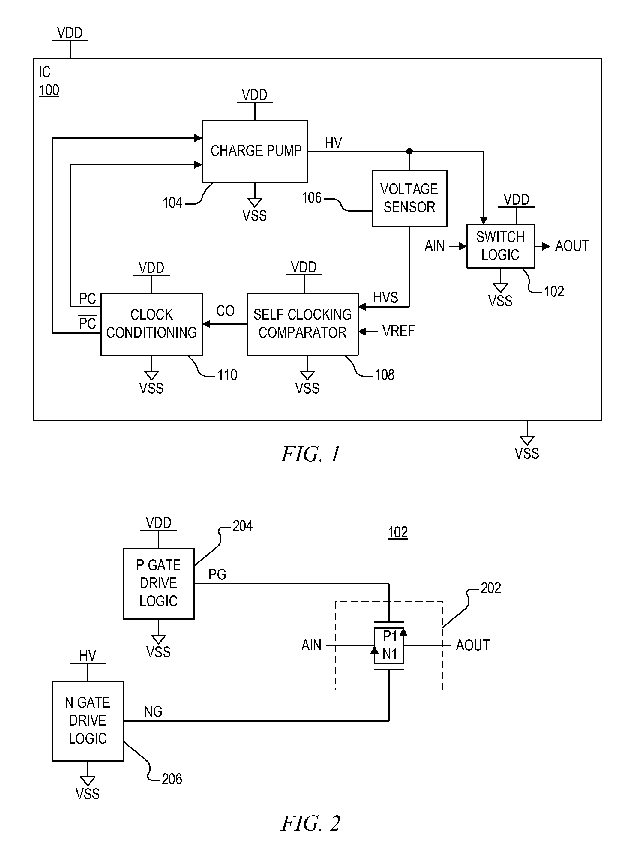
The patent is about a comparator that uses a high voltage output from a charge pump to generate a pump clock for the charge pump. The comparator includes multiple gain stages and a reset circuit that can force the comparator back to its default state when the input voltage is lower than the reference voltage. The comparator also can oscillate the compare voltage at a frequency based on the difference between the input voltage and the reference voltage. The technical effect of the invention is to provide a more accurate and reliable pump clock for the charge pump system.

Problems solved by technology

A charge pump can generate a voltage larger than the supply voltage, but it is challenging to operate one efficiently at low current levels (e.g., in the nanoampere (nA) range).
The comparator has some delay so that when the inputs cross each other such that the output of the comparator is expected to change, there is some delay in time before the comparator output does, in fact, change.
If the voltage excursion is too large, the charge pump output tends to oscillate back and forth causing the control loop to unstable or nearly unstable.
This imposes a limit on how much delay can be tolerated in the comparator to support a given amount of current out of the charge pump.

Method used


Image

  • Self clocking comparator for a charge pump
  • Self clocking comparator for a charge pump
  • Self clocking comparator for a charge pump

Examples


Embodiment Construction

[0021]The benefits, features, and advantages of the present invention will become better understood with regard to the following description, and accompanying drawings. The following description is presented to enable one of ordinary skill in the art to make and use the present invention as provided within the context of a particular application and its requirements.

[0022]A self clocking comparator for a charge pump as described herein integrates pump clock generation with the comparator to increase the maximum clock rate that the comparator can support while also ensuring that the clock runs no faster than this limiting rate. Such integration is achieved by using the output of the self clocking comparator to reset the internal state of the comparator. The comparator is configured to assert its output to a normal or default state when the charge pump output voltage is above a desired reference level. The comparator has a reset input such that when the reset input is asserted, the co...


PUM


Abstract

A self clocking comparator for clocking a charge pump providing a high voltage output including multiple gain stages and a reset circuit. The gain stages are configured to assert the compare voltage at a first voltage level in a default state when the sense voltage is greater than the reference voltage, and to assert the compare voltage to a second voltage level in a reset state when the sense voltage falls below the reference voltage. The reset circuit resets, or otherwise forces, the gain stages back to the default state in response to the compare voltage transitioning to the second voltage level. The compare voltage oscillates while the sense voltage is less than the reference voltage at a frequency based on a magnitude of a difference between the sense voltage and the reference voltage up to a predetermined maximum frequency level.

Description

BACKGROUND OF THE INVENTION[0001]1. Field of the Invention[0002]The present invention relates in general to charge pump configurations, and more particularly to a self clocking comparator for providing pump clocks to drive a charge pump.[0003]2. Description of the Related Art[0004]In order to perform useful functions at a normal chip current level (e.g., on the order of microamperes, μA), it is sometimes useful to generate a voltage larger than the highest supply voltage provided to the chip. This is especially true when the minimum specified supply voltage for the part is quite low. The supply voltage may be as low as 1 to 2 Volts (V), such as, for example, about 1.6 Volts (V). A charge pump can generate a voltage larger than the supply voltage, but it is challenging to operate one efficiently at low current levels (e.g., in the nanoampere (nA) range).[0005]A charge pump may use switched capacitors to generate a voltage higher than the supply voltage. A digital clock is needed to c...

Claims


Application Information

Patent Timeline
Patent Type & Authority Applications(United States)
IPC IPC(8): H03K5/24H03K5/01H02M3/07
CPCH03K5/249H03K5/01H02M3/07
Inventor POWELL, MATTHEW R.
Owner SILICON LAB INC
Learn More