Regulator unit

a technology of a regulator unit and a control unit, which is applied in the direction of fluid pressure control, instruments, process and machine control, etc., can solve the problems of inability to maintain constant lifting or lowering speed of the lifting table, complex and large construction, etc., and achieves simple and compact configuration.

Active Publication Date: 2016-05-19
TAIKOH
View PDF0 Cites 0 Cited by
  • Summary
  • Abstract
  • Description
  • Claims
  • Application Information

AI Technical Summary

Benefits of technology

[0008]An aspect relates to a regulator unit which has a simple and compact configuration, allowing the cylinder pressure to be steplessly changed for lifting or lowering a workpiece at a desired speed, or rapidly positioning the workpiece to stop it at a desired position.

Problems solved by technology

But, since there had existed a difference between such required air pressure, i.e., an air pressure to be constantly varied, and the supplied constant air pressure, the lifting or lowering speed of the lifting table had been incapable of being maintained constant, thereby various inconveniences had been caused.
However, this cylinder pressure adjusting unit presents problems that it has a number of component parts, providing a complex and large construction; especially that the rod of the air cylinder for initial pressure setting is largely protruded, thereby a space covering the protrusion being required; and that it is difficult to steplessly change the cylinder pressure for lifting or lowering the workpiece at a desired speed, or rapidly positioning the workpiece to stop it at a desired position.
As described above, the above-mentioned conventional cylinder pressure adjusting unit has a number of component parts, providing a complex and large construction; the rod of the air cylinder for initial pressure setting is largely protruded, thereby a space covering the protrusion being required; and further it has been difficult to steplessly change the cylinder pressure for lifting or lowering the workpiece at a desired speed, or rapidly positioning the workpiece to stop it at a desired position.

Method used


Image

  • Regulator unit
  • Regulator unit
  • Regulator unit

Examples


Embodiment Construction

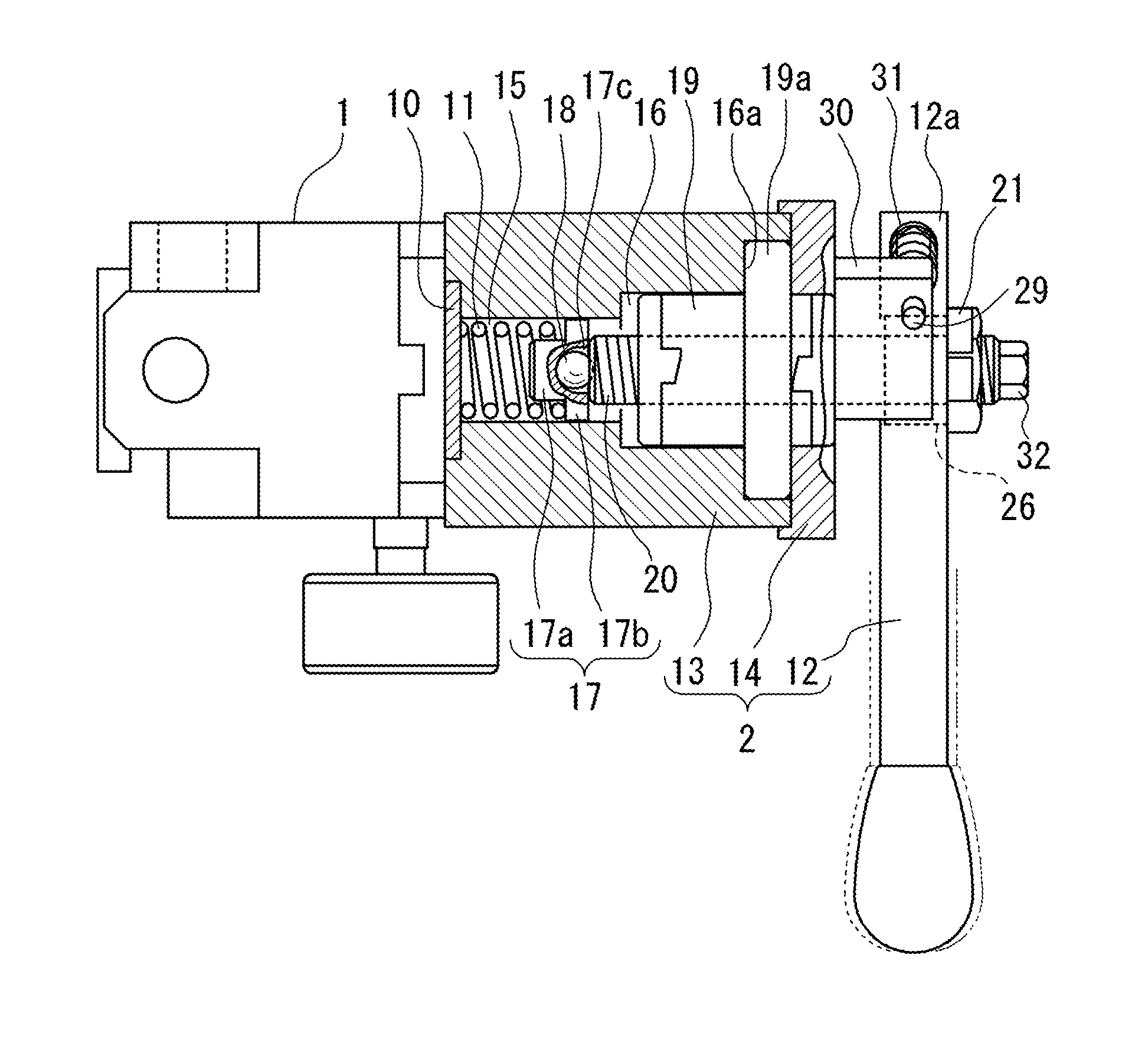
[0019]An embodiment of the present invention will be explained with reference to the attached drawings. A regulator unit in accordance with embodiments of the present invention is disposed between a driving cylinder and a fluid pressure supply source at, for example, an automobile assembling plant, or the like, to control the fluid pressure supplied to a driving cylinder, or the like, for lifting- or lowering-driving a lifting table on which a workpiece is loaded. The fluid pressure is an air pressure or a hydraulic pressure, and here the case where the air pressure is used will be explained, however, also in the case where the hydraulic pressure is used, the same working effects can be obtained.

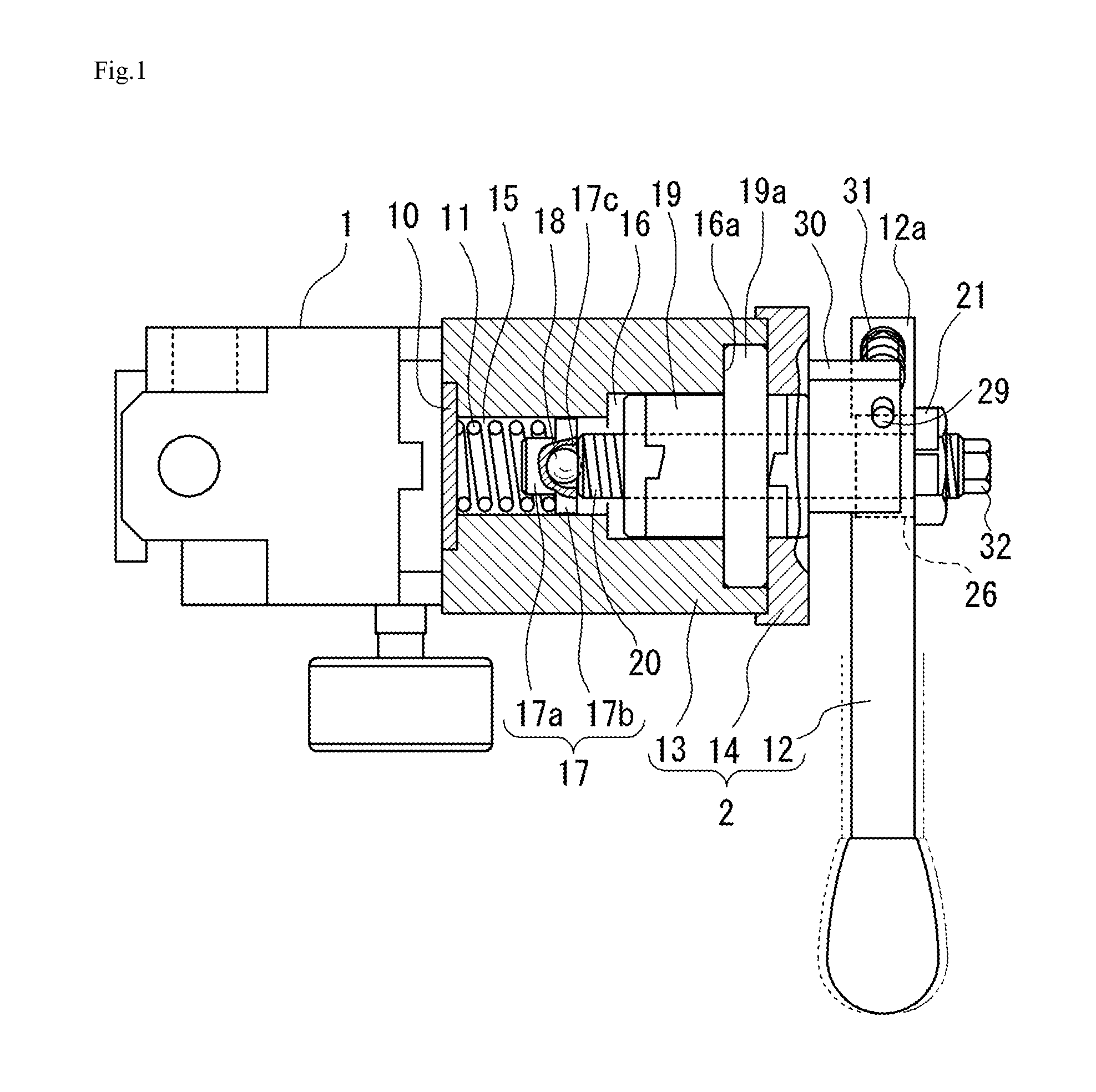
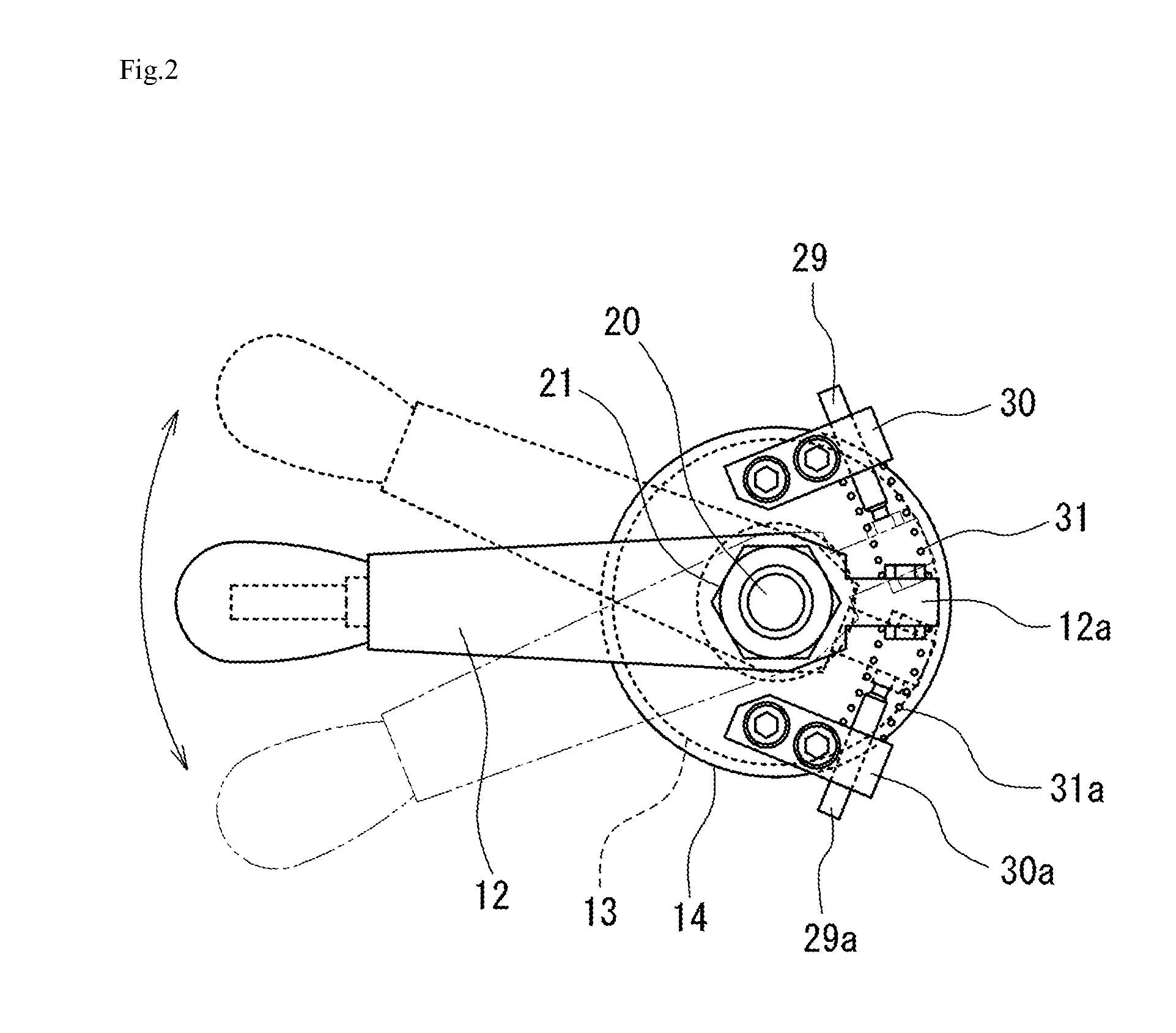
[0020]As shown in FIG. 1, this regulator unit is comprised of a regulator main body 1 and a pressure-regulating mechanism part 2, which is installed consecutively thereto. The regulator main body 1 is disposed in, for example, an air supply passage between a driving air cylinder and an air t...


PUM


Abstract

A regulator unit which includes a regulator main body, and a pressure-regulating mechanism part, being installed consecutively thereto; the pressure-regulating mechanism part being constituted by a cylindrical housing provided with a shouldered hole, the shouldered hole being formed by a smaller-diameter bore and a larger-diameter bore, the smaller-diameter bore accommodating an adjusting spring and an end cover; a ball screw being disposed in the larger-diameter bore; an operation handle being mounted to a basal end part of a threaded rod of the ball screw through a fastener; and the operation handle being capable of being turned for expanding or contracting said adjusting spring to thereby change the spring pressure applied to a diaphragm receiving plate.

Description

CROSS-REFERENCE TO RELATED APPLICATIONS[0001]This application claims priority to PCT Application No. PCT / JP2014 / 068892, having a filing date of Jul. 16, 2014, based on JP Application No. 2013-162589 having a filing date of Aug. 5, 2013, the entire contents of which are hereby incorporated by reference.FIELD OF TECHNOLOGY[0002]The following relates to a regulator unit, and more particularly relates to a regulator unit which, when a lifting table loaded with a workpiece is lifted or lowered with a cylinder at, for example, an automobile assembling plant, or the like, allows obtaining a desired lifting or lowering speed, or stopping the workpiece at a desired position by making a simple operation for controlling the fluid pressure to be supplied to the cylinder.BACKGROUND[0003]For example, with a mechanism using an air cylinder to lift or lower a lifting table on which a workpiece is loaded, as described above, a constant air pressure is supplied to the air cylinder, however, in order ...

Claims


Application Information

Patent Timeline
Patent Type & Authority Applications(United States)
IPC IPC(8): G05D16/06F16K31/60
CPCG05D16/06Y10T137/7793F16K31/602G05D16/0636Y10T137/7809
Inventor ASAI, YASUHARU
Owner TAIKOH
Why Eureka
Try Eureka