Rotor for a centrifugal flow machine and a centrifugal flow machine

a centrifugal flow and rotor technology, applied in the direction of propellers, water-acting propulsive elements, propulsive elements, etc., can solve the problems of impellers not being able to ensure safe use of slide ring seals, user difficulty in manufacturing impellers, and inability to ensure the safety of sealing in all possible operating conditions

Active Publication Date: 2016-05-19
SULZER MANAGEMENT AG
View PDF4 Cites 3 Cited by
  • Summary
  • Abstract
  • Description
  • Claims
  • Application Information

AI Technical Summary

Benefits of technology

[0026]Thus, an object of the present invention is to eliminate at least one of the above mentioned drawbacks or problems by a novel rotor structure of a centrifugal flow machine.
[0027]Another object of the present invention is to develop a novel rotor structure improving the efficiency ratio of the centrifugal flow machine.
[0028]A further object of the present invention is to suggest a novel rotor structure minimizing the axial force across the rotor and thus enabling the application of small bearings for supporting the shaft of the centrifugal flow machine.

Problems solved by technology

The construction of present impellers is not able to ensure safe use of a slide ring seal, as neither the cavity or space for the sealing nor the impeller has been designed such that the sealing would, in all operating conditions of a pump, be totally surrounded by the liquid to be pumped.
Additionally, the various impeller structures have to be chosen in accordance with the liquid to be pumped, and the user cannot be sure that the sealing works in a reliable manner in all possible operating conditions.
The impellers comprise structures, which make the impellers hard to manufacture and decrease the efficiency ratio of the impeller.
Furthermore, balancing arrangements in use at present for balancing the axial forces across the impeller waste a significant part of the efficiency ratio of the impeller.
As a first problem, especially concerning small pumps, of a closed impeller, where the working vanes of the impeller are situated between two shrouds, i.e. a rear and a front shroud, the shrouds take a significant part of the cross-sectional flow area of the flow channel (between the front and rear walls of the volute).
If the semi-open impeller includes balancing holes, the same problems may be seen as with a closed impeller.
And if the semi-open impeller is does not include balancing holes, the same problems may be seen as with a closed impeller, too.
If this construction has no balancing holes through the shroud, the sealing chamber is a dead-end chamber, where the liquid is not able to change and usually gas contained in the liquid is collected in the sealing chamber resulting in that the sealing is running dry.
If the shroud of a semi-open impeller includes balancing holes, the sealing chamber is still a dead-end chamber, where the liquid is not able to change and usually gas contained in the liquid is collected in the sealing chamber resulting in that the sealing is running dry.
In such a construction the sealing chamber is a dead-end chamber, where the liquid is not able to change and usually gas contained in the liquid is collected in the sealing chamber resulting in that the sealing is running dry.
In brief, the various traditional rotor or impeller structures of centrifugal flow machines have a few drawbacks, which complicate the manufacture and use of the flow machines, reduce their efficiency ratio and risk the reliable and trouble-free operation of the shaft sealing.
Firstly, the closed and semi-open impeller have relatively high friction losses and limited cross sectional flow area due to the presence of the at least one shroud.
Also, the efficiency ratio is affected negatively by the existence of the shroud / s.
Secondly, the existence of an axial force subjected to the impeller or rotor requires the use of larger or stronger bearings.
Thirdly, the present prior art impeller structures do not, not even the open impeller, ensure sufficient and reliable flushing of the sealing chamber.

Method used


Image

  • Rotor for a centrifugal flow machine and a centrifugal flow machine
  • Rotor for a centrifugal flow machine and a centrifugal flow machine
  • Rotor for a centrifugal flow machine and a centrifugal flow machine

Examples


Embodiment Construction

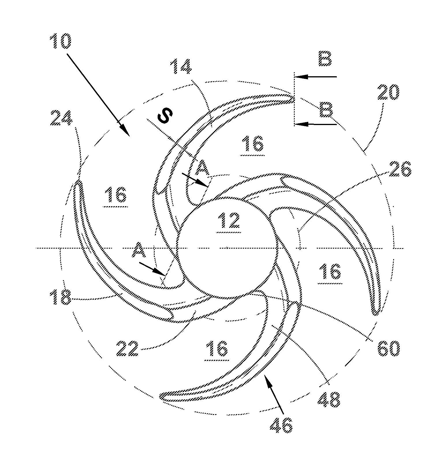
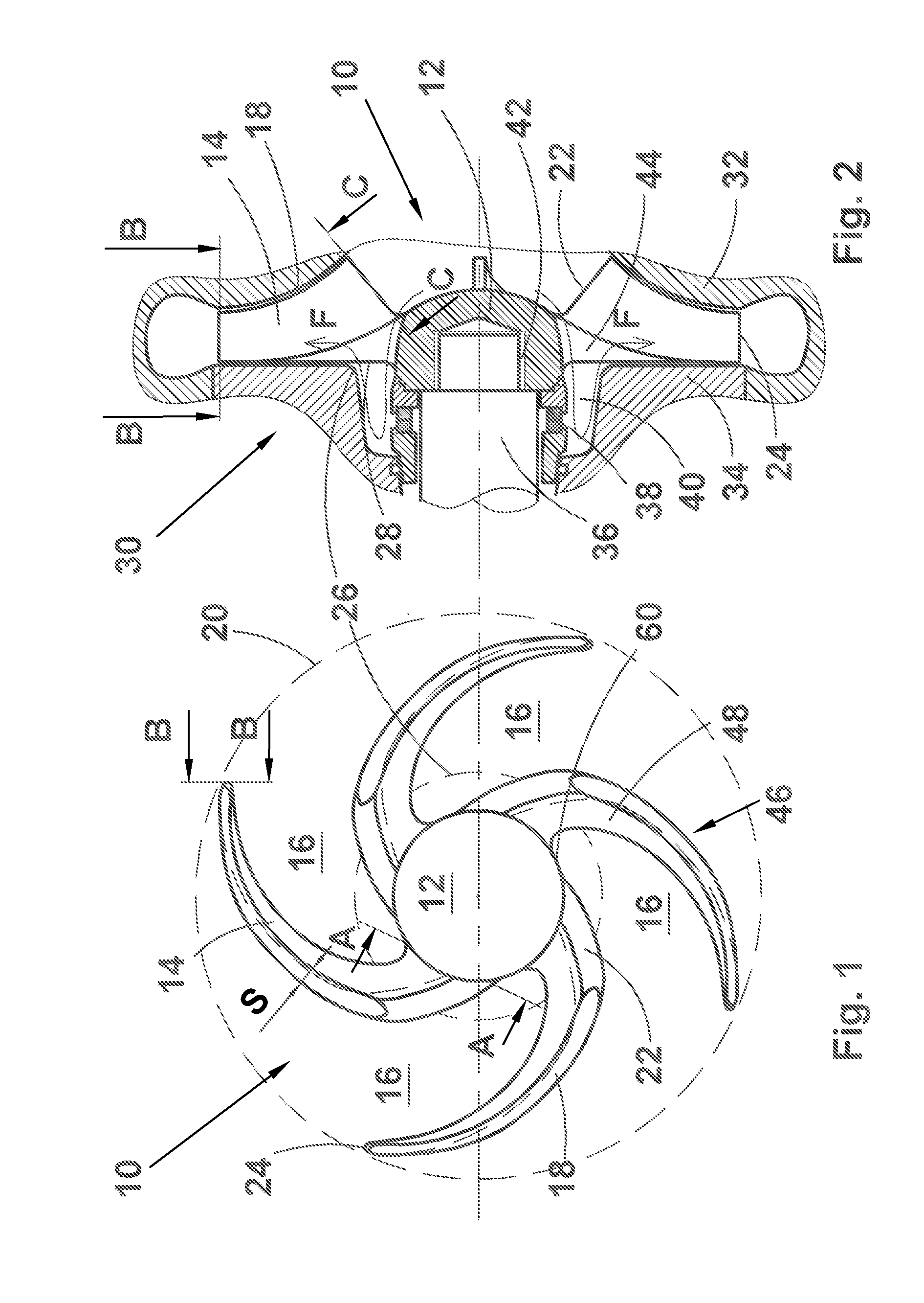
[0050]FIG. 1 illustrates a front view of a rotor in accordance with a preferred embodiment of the present invention. The rotor of FIG. 1 is especially applicable as an impeller of a centrifugal pump. The rotor 10 comprises a hub 12 and four working vanes 14 extending outwardly therefrom. The rotor vanes 14 leave flow chambers 16 there between via which the fluid advances from the inlet opening of a flow machine to the outlet opening thereof. It is an essential feature of the present invention that the flow chambers 18 are open all the way from the outer periphery or circumference (broken circle 20) of the rotor 10 to the outer surface 60 of the hub 12. Preferably, but not necessarily, the outer surface of the hub is a rotationally symmetrical (for instance conical or paraboloidal) surface. In other words, the open impeller of the present invention does not have any support disc extending from the hub for supporting the working vanes. Thus, the fluid has free and open access from the...


PUM


Abstract

A rotor structure for a centrifugal flow machine includes working vanes attached to the hub of the rotor without any support disc or shroud. Additionally, the vane has a device for efficiently flushing the sealing chamber behind the rotor.

Description

CROSS-REFERENCE APPLICATION[0001]This application is a U.S. National Stage Application of International Application No. PCT / EP2014 / 062489, filed Jun. 16, 2014, which claims priority to European Application No. 13174714.9, filed Jul. 2, 2013, the contents of each of which is hereby incorporated herein by reference.BACKGROUND[0002]1. Field of Invention[0003]The present invention relates to a rotor for a centrifugal flow machine and a centrifugal flow machine. The present invention is especially applicable in designing impellers for centrifugal pumps and blowers.[0004]2. Background Information[0005]In the following description of prior art and the present invention, a centrifugal pump has been used as an example of a centrifugal flow machine, and an impeller as an example of a rotor of a centrifugal flow machine. However, it must be borne in mind that the present invention may be used in connection with any centrifugal flow machine i.e. any pumping or blowing apparatus having a rotary ...

Claims


Application Information

Patent Timeline
Patent Type & Authority Applications(United States)
IPC IPC(8): F04D29/22F04D29/28F04D17/08F04D1/00F04D29/24
CPCF04D29/2233F04D1/00F04D29/281F04D29/242F04D17/08F04D29/2266F04D29/126F04D29/245F04D29/28
Inventor MANNINEN, HEIKKI
Owner SULZER MANAGEMENT AG
Why Eureka
Try Eureka