
Chair

Inactive Publication Date: 2016-05-19
ITOKI CORP
View PDF59 Cites 48 Cited by
  • Summary
  • Abstract
  • Description
  • Claims
  • Application Information

AI Technical Summary

Benefits of technology

The present invention improves the comfort of leaning on a chair and ensures the chair's strength while saving time and effort in manufacturing and preventing variations in quality.

Problems solved by technology

There are some factors damaging comfort.
Typically, such factors include a feeling of oppression caused by a situation that the portion hitting the body is hard and a feeling of tightness that the body cannot easily be moved.
Nevertheless, a simple rocking function alone has merely a limited effect in improving comfort.
Nevertheless, in a case that the backrest has a rigid structure, when the person twists the body, the contact area with the backrest decreases so that the user receives a feeling of oppression and hence comfort is degraded.
In a case that the backrest is freely deformed by the body pressure of the seat occupant, the stability of the body is degraded and hence comfort is degraded on the contrary.
In particular, in a case that a person sits on the chair and performs various kinds of desk work, when the person slouches, the internal organs are pressed and hence an intense stress acts on the body.
Nevertheless, since the lower part of the backrest is easily deformed, a high function of firmly supporting the body in a non-rocking state and holding a state that the back is straightened is not expected.
That is, in the individual publicly known documents, there is the possibility of an insufficient function of stably supporting the body in a non-rocking state.
Nevertheless, in the individual publicly known documents, the upper part of the backrest cannot easily be deformed.
For example, when there is a tendency that the body shakes in a rocking state, in some cases, comfort is degraded on the contrary.
In contrast, when the flexibility of the backrest is excessively high, the body cannot stably be supported.

Method used


Image

  • Chair
  • Chair
  • Chair

Examples


Embodiment Construction

[0069]Next, an embodiment of the present invention is described below with reference to the drawings. The present embodiment is applied to a swivel chair widely used in offices or the like. Here, in the embodiment and the claims given below, terms “frontward and rearward” and “right and left” are used for identifying the directions. Then, these directions are defined with reference to a person ordinarily sitting on the chair.

[0070](1). Outlines of Chair

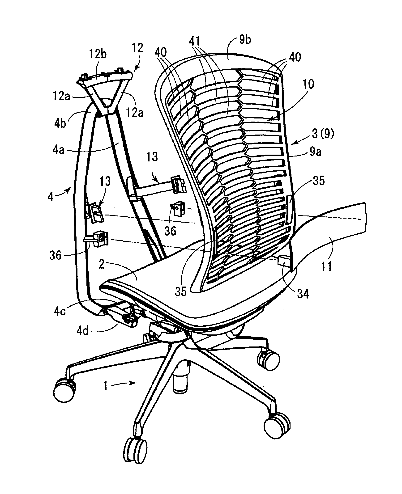
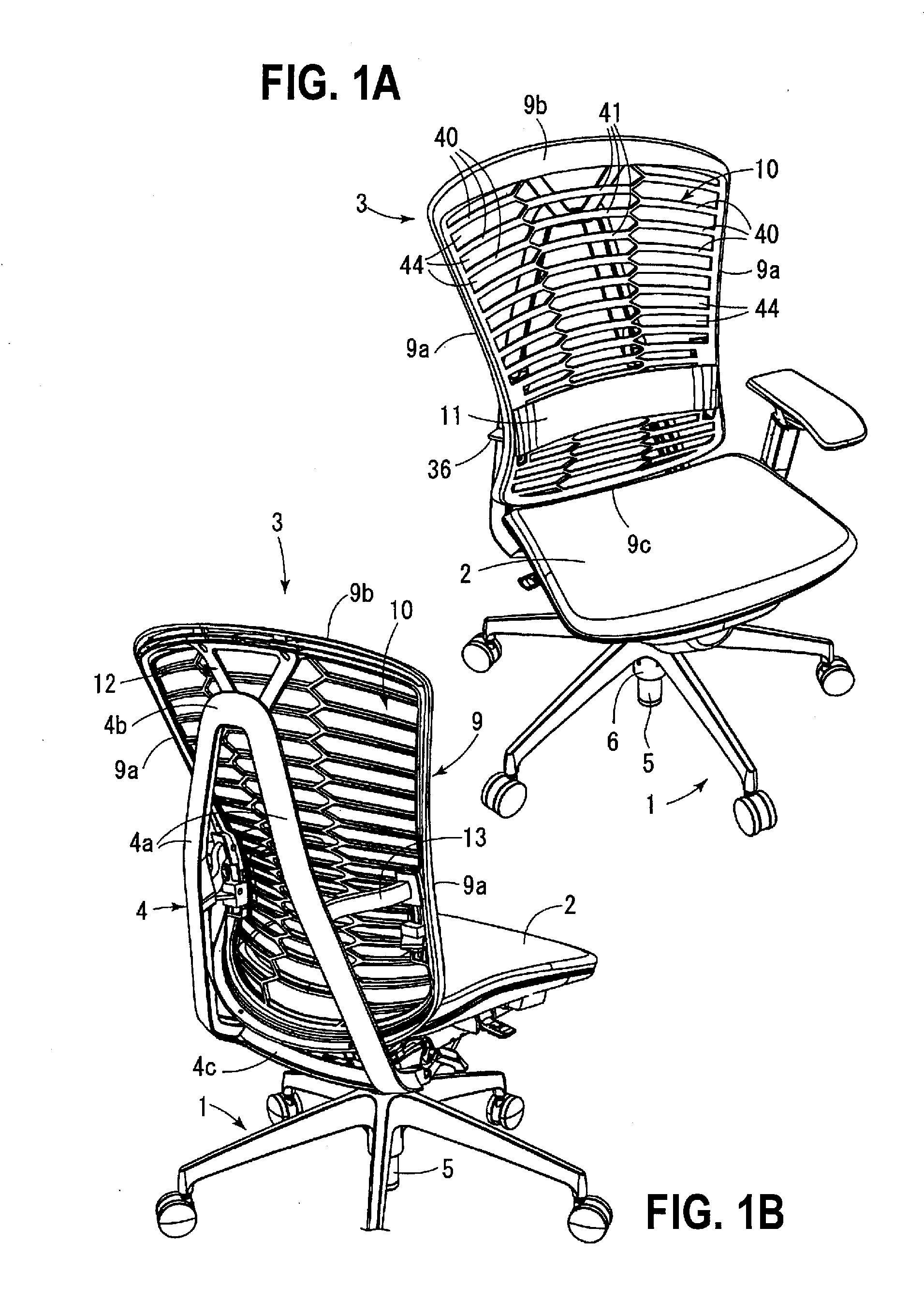
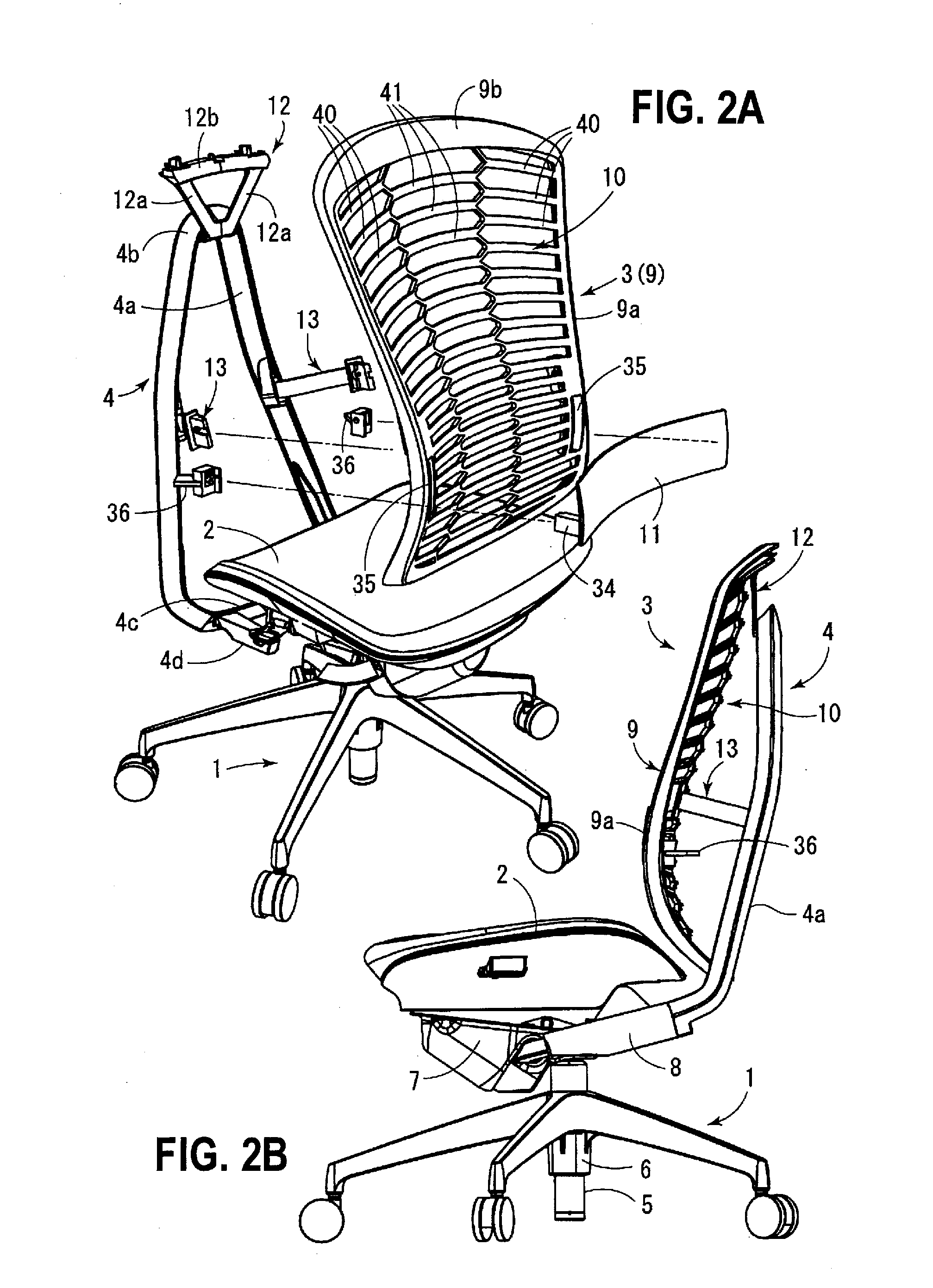
[0071]As shown in FIGS. 1A to 2B, a chair includes as main elements a leg device 1, a seat 2, and a backrest 3. The backrest 3 is attached to a back frame 4 arranged behind it. The leg device 1 includes: a leg pillar 5 in a vertical attitude; and a center tube 6 for supporting this. Five branched arms extend in radial directions from the center tube 6. Then, a caster is attached to the tip of each branched arm.

[0072]The leg pillar 5 is constructed from a gas cylinder of extendable type provided with an inner cylinder and an outer cyli...


PUM


Abstract

A chair includes a seat, a backrest and a back frame having a rigid structure and arranged behind the backrest with an interval in between. The backrest is attached to the back frame by a first support device arranged at a height position close to an upper end of the backrest and by a second support device arranged at a position lower than the first support device and higher than a seat surface. The first support device is attached to a part close to a right-left middle part of the upper end part in the backrest. The second support device is attached to a left end part and a right end part of the backrest.

Description

TECHNICAL FIELD[0001]The present invention relates to a chair and, in particular, treats an office-use chair as a preferred object.BACKGROUND ART[0002]The first factor to be owned by a chair is comfort to a user. In particular, in a chair used in an office, a person continues sitting down for a long time and hence comfort is an important factor. There are some factors damaging comfort. Typically, such factors include a feeling of oppression caused by a situation that the portion hitting the body is hard and a feeling of tightness that the body cannot easily be moved. Thus, countermeasures are taken in order to reduce the feeling of oppression and the feeling of tightness.[0003]The problem of the feeling of oppression is handled such that a cushion is arranged in the seat or the backrest, the seat or the backrest is constructed from a mesh, or the like. Adoption of a deformable structure in the seat plate or the backrest plate is also effective in improving softness.[0004]On the othe...

Claims


Application Information

Patent Timeline
IPC IPC(8): A47C7/44A47C7/46A47C7/36
CPCA47C7/44A47C7/462A47C7/36A47C7/40A47C7/46
Inventor CHAN, ERICKOMOTO, SEITARO
Owner ITOKI CORP
Learn More