
In-band full duplex transceiver

a transceiver and full duplex technology, applied in the field of full duplex transceivers, can solve the problems of wasting resources (time or frequency), requiring additional overhead, and being impossible to apply to a small device, so as to reduce the wideband and the quantization error

Active Publication Date: 2016-05-05
ELECTRONICS & TELECOMM RES INST
View PDF6 Cites 12 Cited by
  • Summary
  • Abstract
  • Description
  • Claims
  • Application Information

AI Technical Summary

Benefits of technology

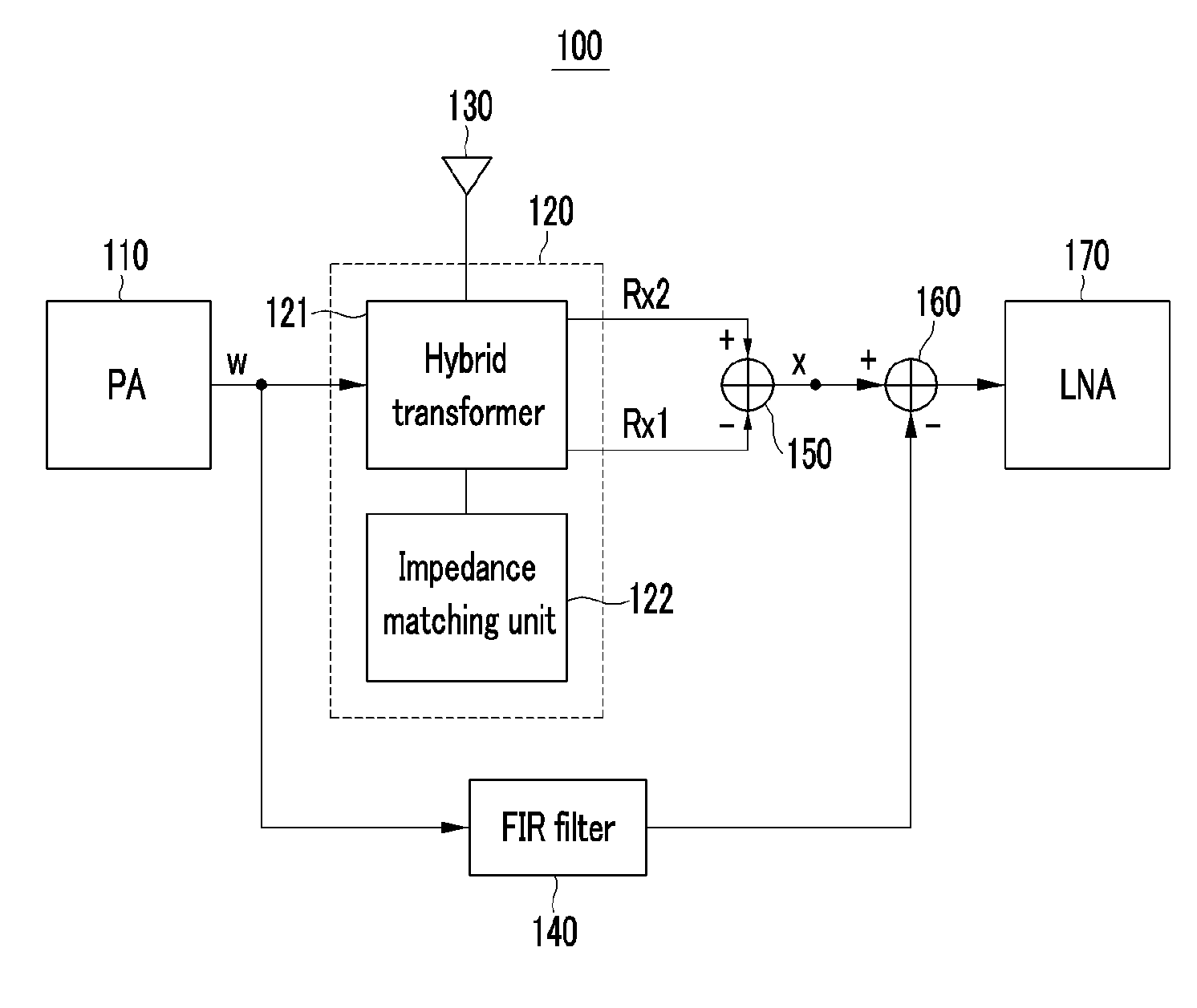
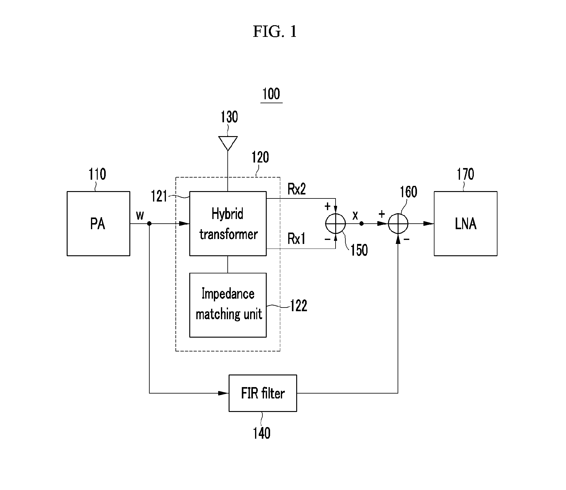
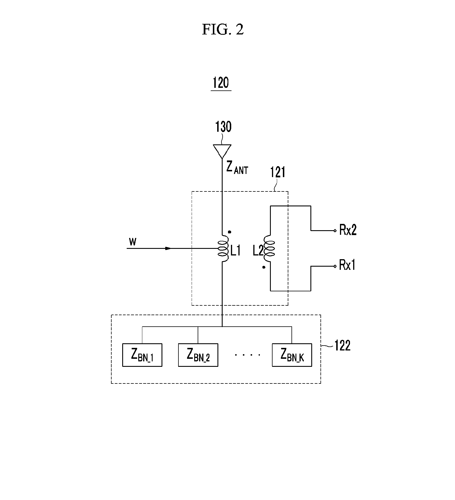
The patent text describes two technical methods to improve the performance of a specific device. The first method involves using multiple balance networks to match impedance and improve the SIC gain (signal-to-interference ratio) in the wideband. The second method involves using a finite impulse response (FIR) filter to cancel out self-transmitting interference signals, reducing both wideband and quantization errors. These techniques can lead to improved performance and reliability of the device.

Problems solved by technology

However, the half duplex method wastes resources (time or frequency), has a problem in a multi-hop relay among mobile small cells, and requires additional overhead to solve a hidden node problem.
However, the in-band full duplex method allows a self-transmitting signal to be input to a receiver so the self-transmitting signal functions as a self-interference signal very strongly compared to a valid received signal, which is a drawback.
A problem of the ICS technique is that it is impossible to be applied to a small device because of the physical separation between the transmitting and receiving antennas.
An electrical balance duplex (EBD) is one of SIC techniques in the in-band full duplex method, but the EBD technique deteriorates SIC performance or destabilizes it as the system bandwidth becomes wider.
That is, the existing EBD technique has a problem in that an SIC gain is great for a specific frequency bandwidth and it becomes less in other frequency bandwidths.

Method used


Image

  • In-band full duplex transceiver
  • In-band full duplex transceiver
  • In-band full duplex transceiver

Examples


Embodiment Construction

[0041]In the following detailed description, only certain exemplary embodiments of the present invention have been shown and described, simply by way of illustration. As those skilled in the art would realize, the described embodiments may be modified in various different ways, all without departing from the spirit or scope of the present invention. Accordingly, the drawings and description are to be regarded as illustrative in nature and not restrictive. Like reference numerals designate like elements throughout the specification.

[0042]Throughout the specification, a transceiver may indicate a terminal, a mobile terminal (MT), a mobile station (MS), an advanced mobile station (AMS), a high-reliability mobile station (HR-MS), a subscriber station (SS), a portable subscriber station (PSS), an access terminal (AT), and user equipment (UE), and it may include entire or partial functions of the terminal, MT, AMS, HR-MS, SS, PSS, AT, and UE.

[0043]The transceiver may represent a base stat...


PUM


Abstract

Disclosed is an in-band full duplex transceiver. The in-band full duplex transceiver may include a transmitter, a hybrid transformer, and an impedance matching unit. The hybrid transformer may include a first end connected to an antenna, may output a transmitting signal to the antenna, and may output a received signal provided through the antenna to the receiver. The impedance matching unit may include balance networks connected to a second end of the hybrid transformer and matching impedance of the antenna.

Description

CROSS-REFERENCE TO RELATED APPLICATION[0001]This application claims priority to and the benefit of Korean Patent Application No. 10-2014-0150693, 10-2014-0160310 and 10-2015-0150168 filed in the Korean Intellectual Property Office on Oct. 31, 2014, Nov. 17, 2014 and Oct. 28, 2015, respectively, the entire contents of which are incorporated herein by reference.BACKGROUND OF THE INVENTION[0002](a) Field of the Invention[0003]The present invention relates to an in-band full duplex transceiver.[0004](b) Description of the Related Art[0005]A current wireless communication system uses a half duplex method. The half duplex method transmits or receives signals by dividing time or frequency so orthogonality between transmitting and receiving may be maintained. However, the half duplex method wastes resources (time or frequency), has a problem in a multi-hop relay among mobile small cells, and requires additional overhead to solve a hidden node problem.[0006]The in-band full duplex method is ...

Claims


Application Information

Patent Timeline
Patent Type & Authority Applications(United States)
IPC IPC(8): H04L5/14H04B15/00H04B1/50
CPCH04L5/14H04B15/00H04B1/50H04B1/0458H04B1/123H04B1/18H04B1/525
Inventor CHANG, KAPSEOKKIM, SEON-AEJU, HYUNG SIKKIM, YOUNGSIK
Owner ELECTRONICS & TELECOMM RES INST
Learn More