Method for producing a rotor

a technology of rotor and rotor body, which is applied in the direction of manufacturing stator/rotor body, magnetic circuit rotating parts, and hybrid vehicle motors, etc., can solve the problems of increasing reducing the size of motors, and reducing the magnetic flux of magnets, so as to reduce the amount of magnet material, reduce the cost of motors, and reduce leakage of magnetic flux

Active Publication Date: 2016-05-05
TOYOTA JIDOSHA KK
View PDF1 Cites 4 Cited by
  • Summary
  • Abstract
  • Description
  • Claims
  • Application Information

AI Technical Summary

Benefits of technology

[0013]The present invention has been made to solve the above problems and has a purpose to provide a method for producing a rotor, including a step of mounting both end portions of a non-magnetic bridge in a pair of dovetail grooves without producing fine friction dust due to rubbing.
[0014]To achieve the above purpose, one aspect of the invention provides a method for producing a rotor including a rotor core provided with a central hole and a magnet hole formed in an outer circumferential portion, a permanent magnet mounted in the magnet hole, and a rotor shaft press-fit in the central hole, wherein the rotor includes: a magnetic flux leakage prevention hole formed in the rotor core to prevent leakage of magnetic flux from the permanent magnet; an outer-circumferential-side dovetail groove formed in an outer-circumferential-side inner wall defining the magnetic flux leakage prevention hole on an outer circumferential side and an inner-circumferential-side dovetail groove formed, opposite the outer-circumferential-side dovetail groove, in an inner-circumferential-side inner wall defining the magnetic flux leakage prevention hole on an inner circumferential side; and a non-magnetic bridge having both end portions being wide-width portions individually engageable with the outer-circumferential-side dovetail groove and the inner-circumferential-side dovetail groove, and wherein the method includes: applying an external force to the rotor core to cause elastic deformation of the rotor core so that the outer-circumferential-side inner wall o

Problems solved by technology

Motors for hybrid vehicles and others are severely demanded for size reduction more than regular motors.
Such a motor is more likely to cause a decrea

Method used


Image

  • Method for producing a rotor
  • Method for producing a rotor
  • Method for producing a rotor

Examples


Embodiment Construction

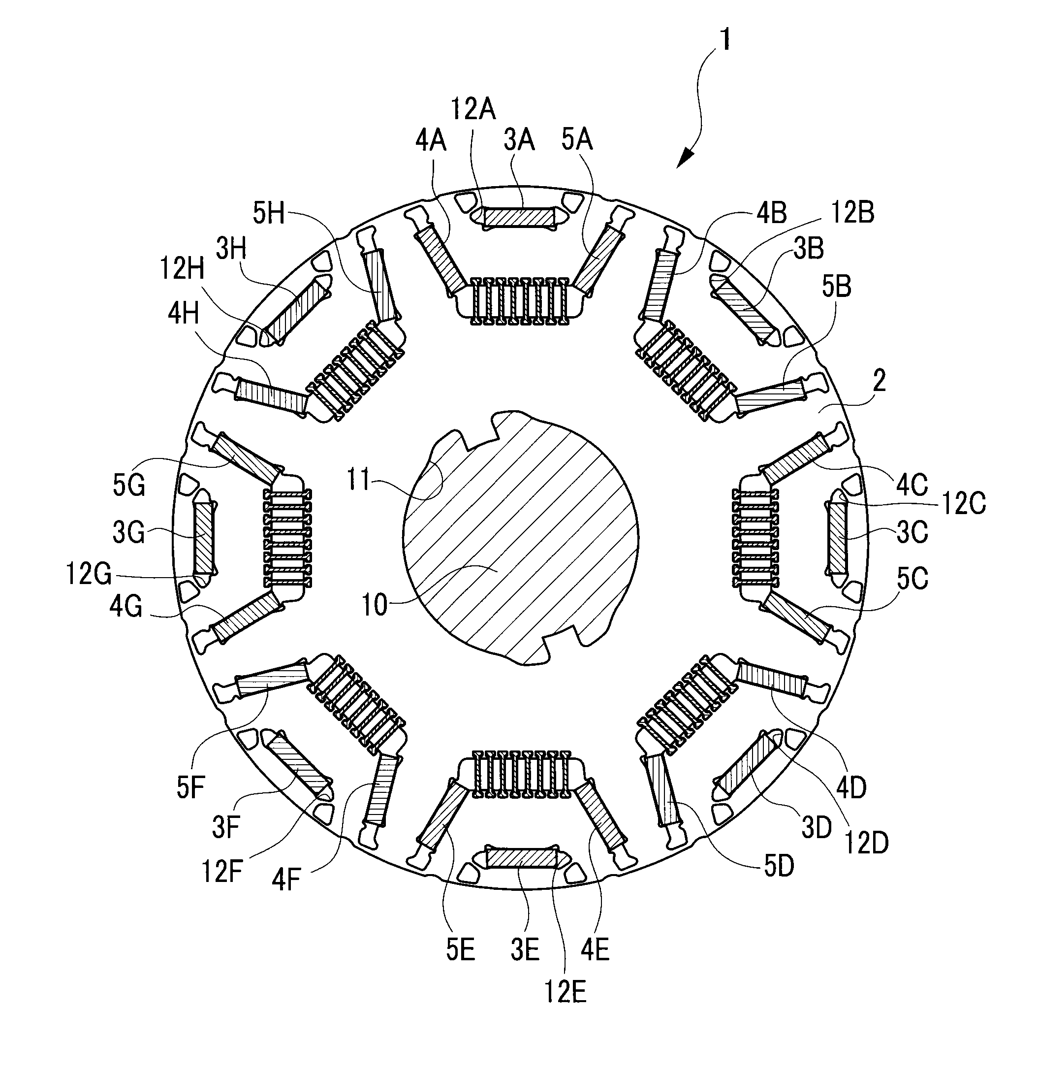
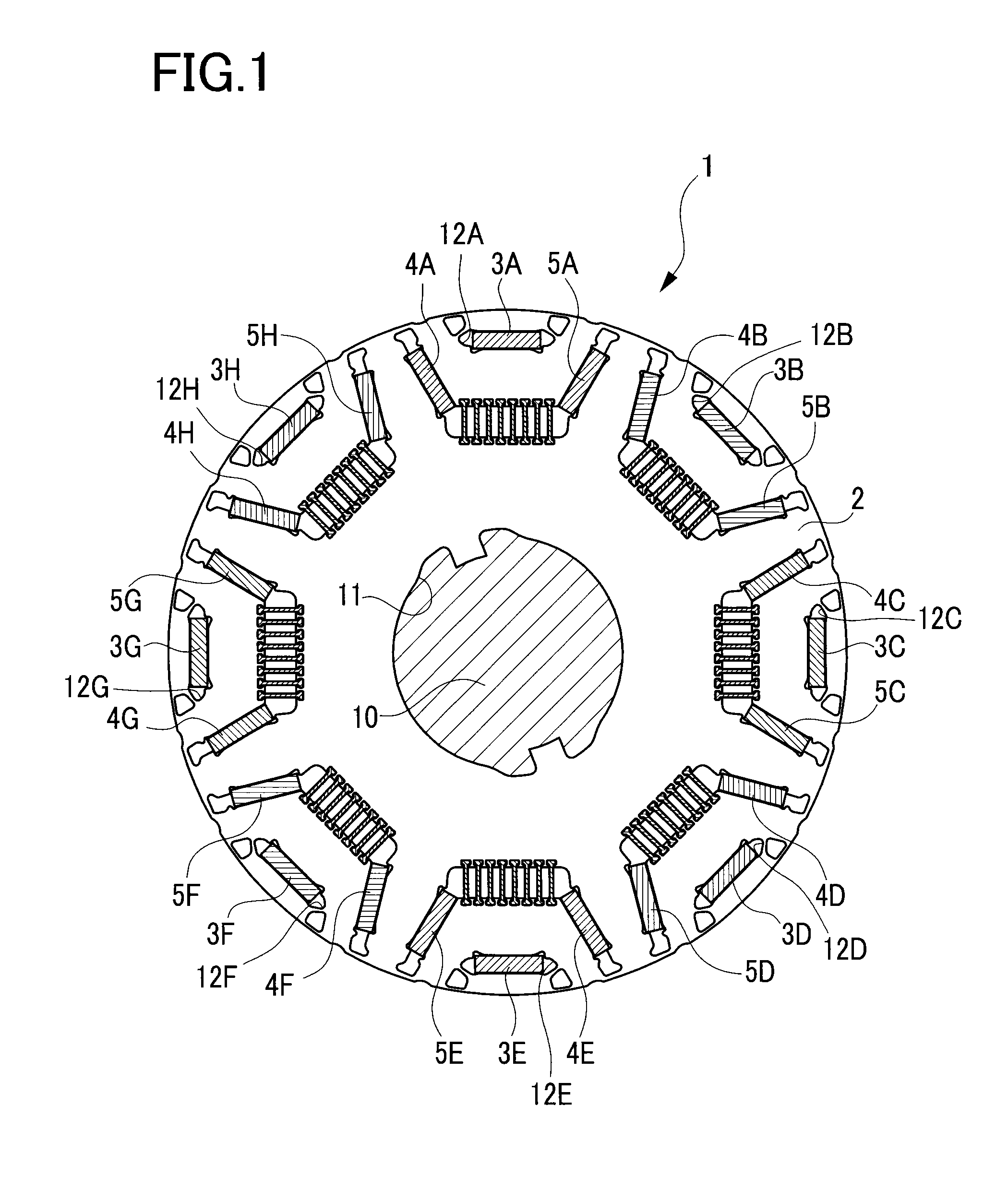
[0027]A detailed description of a preferred embodiment of a method for producing a rotor core will now be given referring to the accompanying drawings. FIG. 1 is a configuration view of a rotor 1. FIG. 2 is a partial enlarged view of the rotor 1. FIG. 3 is a view of the rotor 1 of FIG. 2, in which permanent magnets 3, 4, and 5 and non-magnetic bridges 6 are unmounted.

[0028]A rotor core 2 is made of stacked or laminated several hundred thin plates produced by way of punching a magnetic steel plate having a thickness 0.1 to 0.3 mm by a press. Each thin plate is formed with a plurality of dowels in half-cut shape not shown so that the thin plates are stacked one on another with a projection of each dowel being fitted in a recess of each adjacent dowel. Accordingly, first magnet holes 12, second magnet holes 13, third magnet holes 14, and others are formed with respective inner wall surfaces accurately aligned.

[0029]In a central hole 11 of the rotor core 2, a rotor shaft 10 is fitted. I...


PUM


Abstract

In a method for producing a rotor including a leak prevention hole formed in a rotor core to prevent leakage of magnetic flux from a permanent magnet; an outer-circumferential-side dovetail groove formed in an outer-circumferential-side inner wall of the leak prevention hole, an inner-circumferential-side dovetail groove formed, opposite the outer-circumferential-side dovetail groove, in an inner-circumferential-side inner wall of the leak prevention hole; and a non-magnetic bridge having both end portions engageable with the dovetail grooves, an external force is applied to bring the outer-circumferential-side inner wall close to the inner-circumferential-side inner wall, the non-magnetic bridge is inserted in the dovetail grooves while keeping the rotor core in an elastically deformed state, and, after inserting, the external force is released.

Description

CROSS-REFERENCE TO RELATED APPLICATIONS[0001]This application is based upon and claims the benefit of priority from the prior Japanese Patent Application No. 2014-225339, filed Nov. 5, 2014, the entire contents of which are incorporated herein by reference.BACKGROUND OF THE INVENTION[0002]1. Field of the Invention[0003]The present invention relates to a method for producing a rotor including a rotor core provided with a central hole and a hole for magnet (a magnet hole) formed in an outer circumferential portion, a permanent magnet mounted in the magnet hole, and a rotor shaft press-fitted in the central hole.[0004]2. Related Art[0005]Motors for hybrid vehicles and others are severely demanded for size reduction more than regular motors. Downsized motors tend to rise in temperature. Such a motor is more likely to cause a decrease in magnetic flux of a magnet at high temperature than in conventional motors. To prevent this decrease in magnetic flux density at high temperature, magnet...

Claims


Application Information

Patent Timeline
IPC IPC(8): H02K15/03H02K1/28H02K15/00H02K1/27
CPCH02K15/03H02K15/0018H02K1/28H02K1/276H02K1/2766Y10T29/49012
Inventor HAMANAKA, IPPEIHIRAO, YASUYUKIKINOSHITA, YASUO
Owner TOYOTA JIDOSHA KK
Why Eureka
Try Eureka