
Network configuration and operation visualizing apparatus

a network configuration and operation technology, applied in the field of network management techniques, can solve the problems of network administrator's difficulty in coping, inability to maximize network performance appropriate for information services, and difficulty for general users to adjust networks in accordance with their/her applications

Active Publication Date: 2016-04-28
NAT INST OF INFORMATION & COMM TECH
View PDF5 Cites 66 Cited by
  • Summary
  • Abstract
  • Description
  • Claims
  • Application Information

AI Technical Summary

Benefits of technology

The present invention is a device that helps users see a clear view of the network layout and its activities. This device is designed to make it easy for users to monitor and analyze the network.

Problems solved by technology

On the other hand, thus far, only a few experts could adjust configurations of such networks and it has been very difficult for a general user to adjust a network in accordance with his / her applications.
When an unexpected event occurs, even a network administrator finds it difficult to cope with it.
On the one hand, when an application developer wishes to create a new service cooperation on-demand, only the network paths that have already been set can be used, and hence, it is impossible to maximize network performance appropriate for the information service.
On the other hand, a network administrator builds a network under conditions assumed in advance and, therefore, if a trouble such as unexpected traffic overloads on an assumed path occurs, it is difficult to address the problem on highly real-time basis.
Since a huge number of devices are connected to the network, it is impossible by text information to comprehend such type of information.

Method used


Image

  • Network configuration and operation visualizing apparatus
  • Network configuration and operation visualizing apparatus
  • Network configuration and operation visualizing apparatus

Examples


Embodiment Construction

[0035]In the following description and in the drawings, the same components are denoted by the same reference characters. Therefore, detailed description thereof will not be repeated.

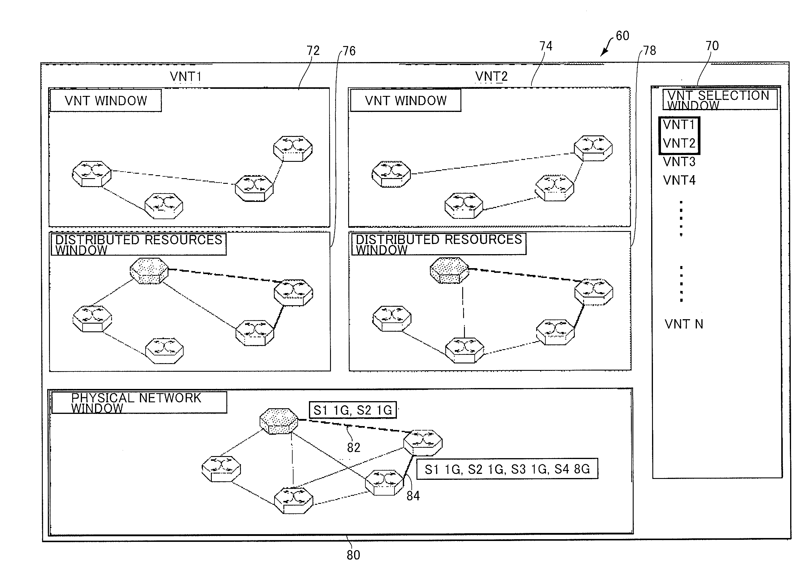
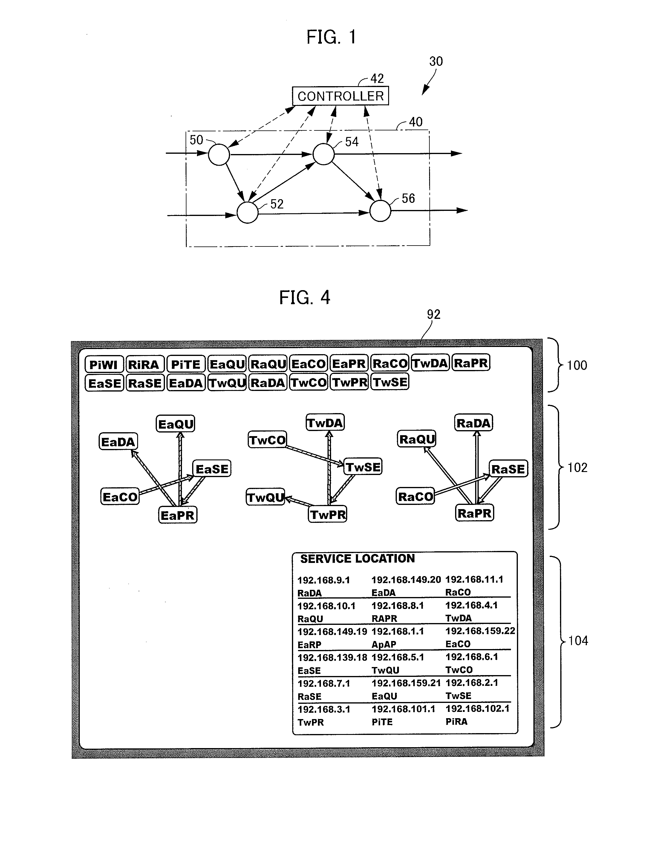
[0036]Referring to FIG. 3, a monitoring screen 90 of a network visualizing apparatus in accordance with an embodiment of the present invention includes an execution monitoring window 92 of service cooperations built on the network as an object of monitoring. Configuration of service cooperation is described as a set of rules by declarative descriptions referred to as DSN, as will be discussed later. Each rule includes a condition or a set of conditions to be satisfied by a network status and an information service status and a process to be executed when the condition or the set of conditions are satisfied (when the rule is fired). Any of the processes defines a process of generating a network control command of OpenFlow.

[0037]The network management system includes middleware, which will be described la...


PUM


Abstract

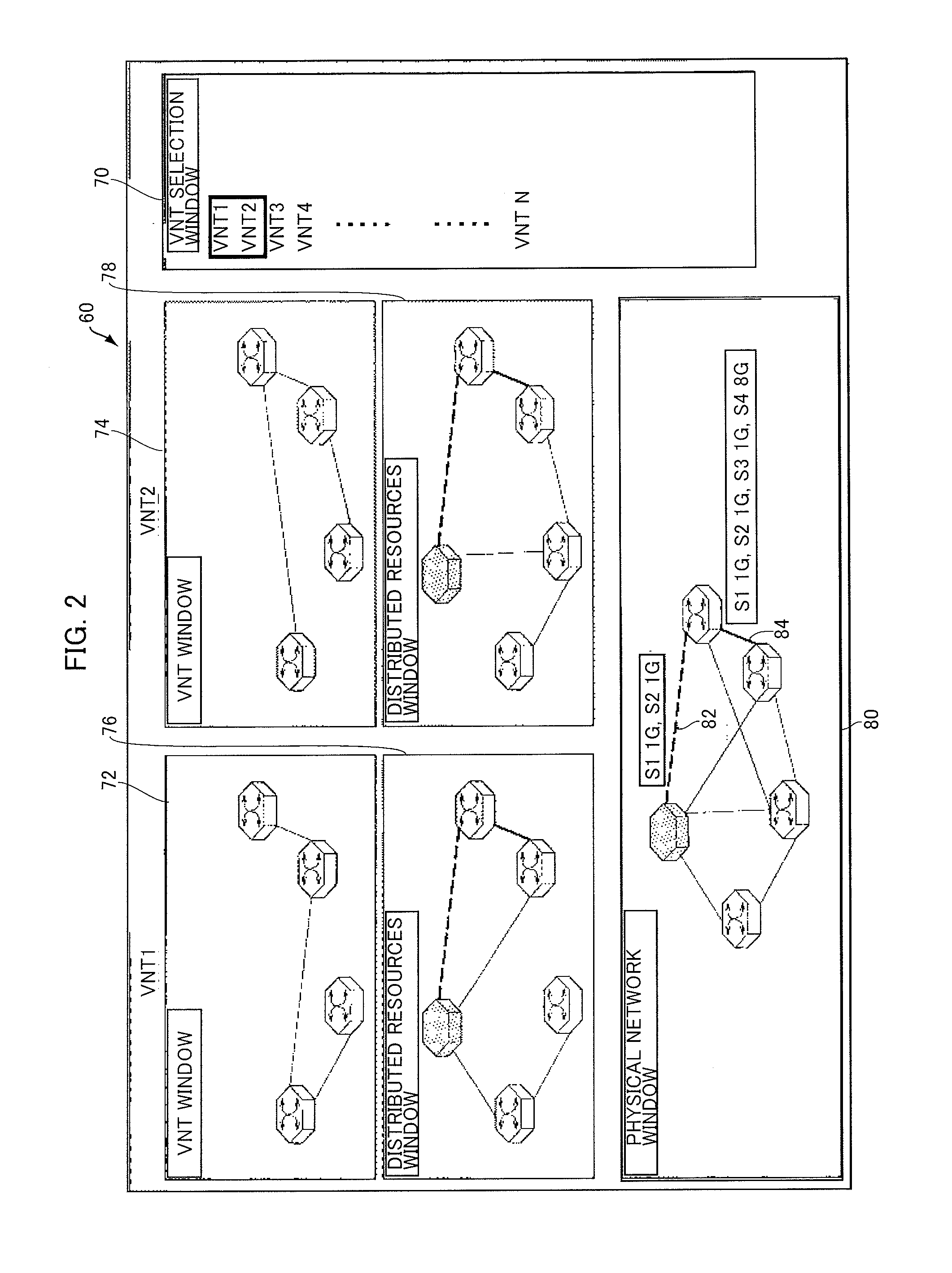
[Object] To provide a network visualizing apparatus giving a user to have a clear perspective of network configuration and operation.[Solution] The visualizing apparatus for monitoring a network having logical configuration changeable by software interpreting a network control command includes a display device 98, a first drawing unit drawing a first image 92 representing cooperation between services provided on the network on the display device 98, and a second drawing unit drawing a second image 98 representing what connection between which node and which switch realizes the service cooperation on the network, on the display device. The first and second drawing units update drawings of a service cooperation execution monitoring window 92 and a network configuration monitoring window 98, respectively, in a synchronized manner. A log 94 representing result of interpretation of descriptions describing cooperation between services and a log 96 representing network status may also be displayed in a synchronized manner.

Description

TECHNICAL FIELD[0001]The present invention relates to a network management technique and, more specifically, to a network monitoring technique giving a clear perspective of various information services and behaviors of a physical network, in a Service Controlled Networking technique (hereinafter referred to as “SCN”) for dynamically modifying a configuration of the physical network to satisfy requests from various information components (hereinafter referred to as “information services”) arranged in a network space.BACKGROUND ART[0002]Development of infrastructures for data communication networks has enabled applications to use high processing performances of networks. Such networks are highly scalable and, hence, various and many information services will definitely be made available through the networks in the future.[0003]On the other hand, thus far, only a few experts could adjust configurations of such networks and it has been very difficult for a general user to adjust a netwo...

Claims


Application Information

Patent Timeline
IPC IPC(8): H04L12/26G06T11/20G06F3/0481H04L45/42
CPCH04L43/045G06T2200/24G06T11/206G06F3/0481H04L41/0806H04L41/22H04L41/40H04L41/0895H04L41/122H04L41/12
Inventor MURASATO, HIDEKIKIMATA, TAKASHITOYOMURA, TETSUOZETTSU, KOJI
Owner NAT INST OF INFORMATION & COMM TECH
Learn More