
Magnetic resonance imaging method and apparatus

a magnetic resonance imaging and magnetic resonance technology, applied in the direction of image enhancement, measurement using nmr, instruments, etc., can solve the problems of reducing the efficiency of scanning sequences, unable to carry out scan sequences, etc., and achieve the effect of improving scanning efficiency

Active Publication Date: 2016-04-28
SIEMENS HEALTHCARE GMBH
View PDF3 Cites 8 Cited by
  • Summary
  • Abstract
  • Description
  • Claims
  • Application Information

AI Technical Summary

Benefits of technology

This patent describes techniques for improving magnetic resonance imaging (MRI) by increasing the efficiency of scanning and allowing for more flexible selection of scan parameters. These techniques can lead to higher quality MRIs and shorter overall scan times. The application of these techniques can also help improve the usability of MRI by providing useful information to the user and preventing faulty diagnoses. Furthermore, the patent describes a method for optimizing the information content in MRI by reducing the amount of information in certain areas of the image. This can improve the overall quality and make the image easier to interpret for the user.

Problems solved by technology

Technical and physiological limitations play a large part in a number of techniques for MR imaging.
In general, limitations of this type lead to a restriction of the efficiency when a corresponding scan sequence is carried out; this can be because particular scan parameters of the scan sequence cannot be selected, or can be selected only to a limited extent.
If an overshoot is determined, the scan sequence cannot be carried out.

Method used


Image

  • Magnetic resonance imaging method and apparatus
  • Magnetic resonance imaging method and apparatus
  • Magnetic resonance imaging method and apparatus

Examples


Embodiment Construction

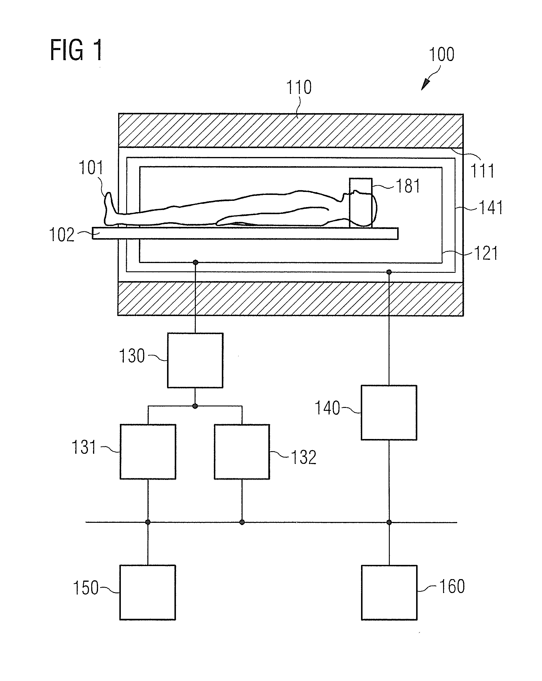
[0069]The present invention will now be described in greater detail on the basis of preferred embodiments and making reference to the drawings. In the drawings, the same reference signs denote the same or similar elements. The figures are schematic representations of different embodiments of the invention. Elements shown in the drawings are not necessarily shown to scale. Rather, the different elements shown in the drawings are reproduced so that their function and general purpose are comprehensible to a person skilled in the art. The links and couplings shown in the figures between the functional units and elements can also be implemented as indirect links or couplings. A link or coupling can be implemented wire-bound or wirelessly. Functional units can be implemented as hardware, software or a combination of hardware and software.

[0070]Techniques that enable an improved scan sequence for determining an MR image which maps an examination region will now be illustrated. According to...


PUM


Abstract

A magnetic resonance image is generated by executing a scan sequence that is determined by at least one scan parameter. A first value of the at least one scan parameter is determined for a first subregion of an examination region, and a second value of the at least one scan parameter is determined for a second subregion of the examination region. The determination of the first value and the determination of the second value is implemented so that a value of a physical variable influenced by the first value and the second value of the at least one scan parameter does not transgress a pre-set threshold value. Subsequently, the scan sequence is executed by a magnetic resonance scanner and a magnetic resonance image is generated. The threshold value can be based, for example, on technical efficiency of the scanner and / or a physiological limitation of an examination object.

Description

BACKGROUND OF THE INVENTION[0001]1. Field of the Invention[0002]Different embodiments of the invention concern a method and system for generating a magnetic resonance image. In particular, different embodiments of the invention concern techniques by which a value of a scan parameter that determines the scan sequence is determined for a first subregion and a second subregion of an examination region.[0003]2. Description of the Prior Art[0004]In magnetic resonance (MR) imaging, structures in an examination region of an examination object, for example, a patient, can be made visible. One type of MR imaging is MR spectroscopy. With MR spectroscopy, particular result values, for example, a fat or water proportion of a tissue, can be determined and made visible.[0005]Technical and physiological limitations play a large part in a number of techniques for MR imaging. In general, limitations of this type lead to a restriction of the efficiency when a corresponding scan sequence is carried ou...

Claims


Application Information

Patent Timeline
IPC IPC(8): G01R33/54G01R33/36G01R33/30G06T7/00G01R33/56
CPCG01R33/543G06T7/0012G01R33/56G06T2207/10088G01R33/36G01R33/546G01R33/30G01R33/288G01R33/4835
Inventor FEIWEIER, THORSTEN
Owner SIEMENS HEALTHCARE GMBH
Learn More