
Vacuum Air Pump and Glass-Wiping Apparatus

a vacuum air pump and glass-wiping technology, which is applied in the direction of piston pumps, positive displacement liquid engines, machines/engines, etc., can solve the problems of loss of vacuum degree, machine body falling off the glass surface, and larger shaft length, so as to increase the number of piston air pump members, increase the air flow rate of the air pump, and keep the structure simple and compact

Inactive Publication Date: 2016-04-21
ECOVACS COMML ROBOTICS CO LTD
View PDF5 Cites 0 Cited by
  • Summary
  • Abstract
  • Description
  • Claims
  • Application Information

AI Technical Summary

Benefits of technology

The present invention provides a vacuum air pump and glass-wiping device that can increase the air flow rate without losing vacuum quickly. The vacuum air pump has a simple and compact structure and allows for an increased number of piston air pump members as needed. The rolling element (e.g. bearing or roller) reduces wear and the air pump's structure ensures uniform and stable movement of the piston rods and reduces the volume in the shaft direction. This glass-wiping device effectively prevents the machine body from falling off the glass surface.

Problems solved by technology

The above vacuum air pump uses only a pair of pistons for vacuum pumping and thus the air flow of the air pump is small, and if the suction cup is lifted by particles on the glass surface, it will lose the vacuum degree soon, thereby making the machine body fall off the glass surface.
As a result, the vacuum air pump will have a larger shaft length, and thus has a complicated and non-compact structure, which will significantly affect the appearance and volume of the glass-wiping robot.

Method used


Image

  • Vacuum Air Pump and Glass-Wiping Apparatus
  • Vacuum Air Pump and Glass-Wiping Apparatus
  • Vacuum Air Pump and Glass-Wiping Apparatus

Examples


first embodiment

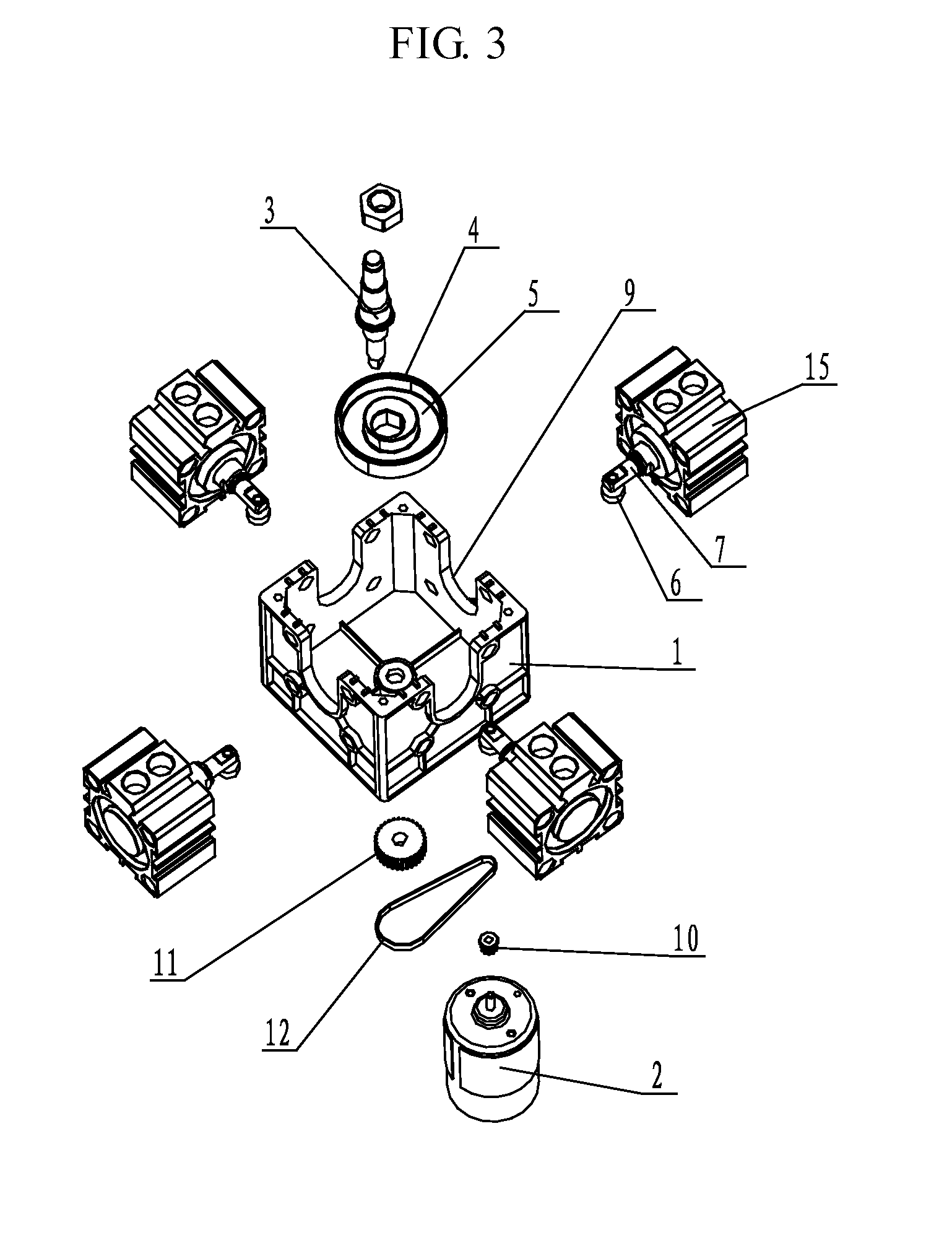
[0025]FIG. 3 is an exploded structural view of the first embodiment of the present invention; FIG. 4 is a sectional view of the first embodiment of the present invention; and FIG. 5 is a structural view of an assembly of the first embodiment of the present invention. As shown in FIGS. 3 to 5, the present invention provides a vacuum air pump comprising a driving motor 2, an air pump body 1 and a piston air pump member 15 provided on the air pump body 1, wherein a rotating shaft 3 is provided in the air pump body 1, the driving motor 2 transmits power to the rotating shaft 3 through a transmission mechanism, and a rotating wheel is fixed on the rotating shaft 3. A diameter-variable annular limitation groove 5 is formed on one side surface of the rotating wheel and may use various shapes, and in the present embodiment, the rotating wheel is an eccentric wheel 4 and thus the diameter-variable annular limitation groove 5 formed on one side surface of the eccentric wheel 4 is round. Four ...

second embodiment

[0029]FIG. 6 is a structural view of the assembly of the second embodiment of the present invention. As shown in FIG. 6, the difference of the present embodiment from the first embodiment is: in the present embodiment, the piston air pump members 15 are provided in three pairs, i.e., six piston air pump members 15 indicated by the numbers 1 to 6 are provided uniformly around the air pump body 1. For the reason that the number of the piston air pump members 15 becomes greater, the outer shape of the air pump body 1 is a cylinder, for ease of arrangement.

[0030]In addition, the transmission mechanism in the present embodiment has a different structure from that of the first embodiment, and comprises a driving gear provided on the shaft of the driving motor 2 and a driven gear provided on the rotating shaft 3, wherein the driving gear and the driven gear are engaged with each other.

[0031]Other technical features of the present embodiment are substantially the same as those of the first ...

third embodiment

[0032]FIG. 7 is a structural view of a diameter-variable annular limitation groove of the third embodiment of the present invention. As shown in FIG. 7, the diameter-variable annular limitation groove in the present embodiment is an irregularly-shaped groove 1000. The piston air pump members 15 are provided around the air pump body in plural pairs, the piston rod 7 of each of the piston air pump members 15 is provided with a rolling element at the end, the rolling element is embedded in the irregularly-shaped groove 1000, the rotating shaft drives the rotating wheel to rotate, and the rolling element rolls within the irregularly-shaped groove 1000 in the circumferential direction of the rotating shaft to thereby drive the piston rod 7 to make a reciprocating movement depending on the size change in radius of the irregularly-shaped groove 1000.


PUM


Abstract

A vacuum air pump and a glass-wiping device are provided. The air pump comprises a driving motor (2), an air pump body (1) and a piston air pump member (15), a rotating shaft (3) is provided in the air pump body, the driving motor transmits power to the rotating shaft via a transmission mechanism, a rotating wheel is fixed on the rotating shaft, a diameter-variable annular limitation groove (5) is formed in the rotating wheel; at least two piston air pump members are provided around the air pump body, a piston rod of each of the members is provided with a rolling element (6) at the end thereof, the rolling element is embedded in the annular limitation groove, the rotating shaft drives the rotating wheel to rotate, and the rolling element rolls within the diameter-variable annular limitation groove in the circumferential direction of the rotating shaft to thereby drive the piston rod (7) to make a reciprocating movement depending on the size change in radius of the diameter-variable annular limitation groove. The present invention may change the number of the piston air pump members so as to keep the structure simple and compact while increasing the air flow rate of the air pump, the piston rod performs a reciprocating movement uniformly and stably, and a plurality of pairs of the piston air pump members are installed at the same height, thereby reducing the volume in the shaft direction of the vacuum air pump.

Description

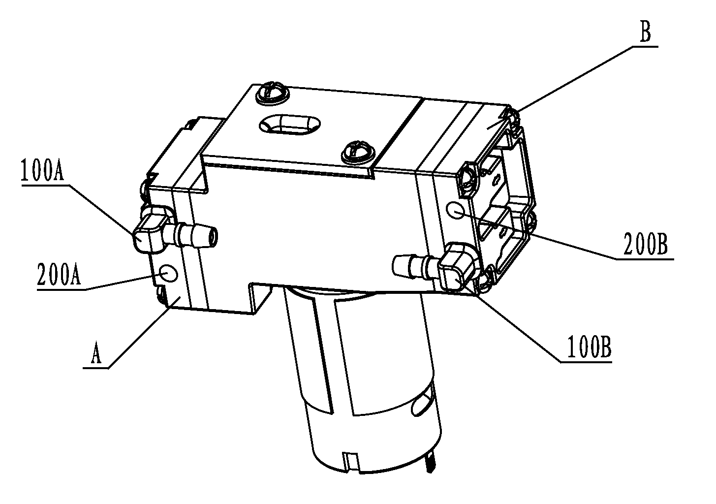
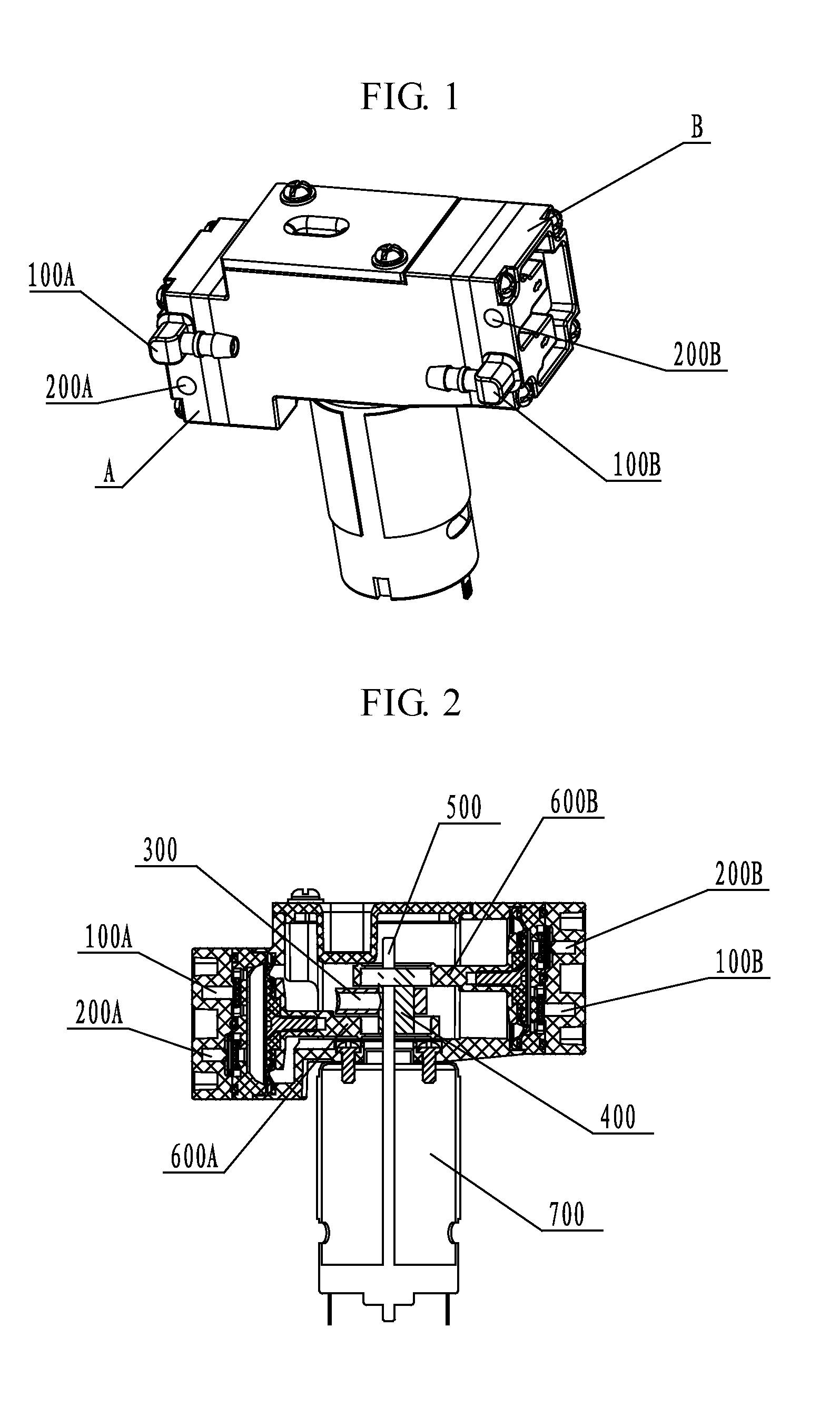
FIELD OF THE INVENTION[0001]The present invention relates to a vacuum air pump and a glass-wiping device, belonging to the technical field of mechanical manufacturing.BACKGROUND OF THE PRIOR ART[0002]A glass-wiping robot in the prior art automatically cleans a glass by allowing a suction cup on the bottom of the machine body to be adsorbed onto the glass. The vacuum degree in the suction cup is generated by the vacuum air pump constantly performing pumping. The vacuum air pump in the prior art generally accomplishes the vacuum-pumping motion such that a motor drives two symmetrically installed pistons to perform reciprocating movement. FIG. 1 is a structural perspective view of the vacuum air pump in the prior art; and FIG. 2 is a sectional view of the vacuum air pump in the prior art. As shown in FIG. 1 in combination with FIG. 2, the vacuum air pump includes two cylinders A and B each having one air inlet hole 100A or 100B and one air outlet hole 200A or 200B, wherein the air inle...

Claims


Application Information

Patent Timeline
Patent Type & Authority Applications(United States)
IPC IPC(8): A47L7/00F04B37/14F04B35/01
CPCA47L7/009F04B37/14F04B35/01A47L1/02
Inventor FENG, YONGBING
Owner ECOVACS COMML ROBOTICS CO LTD
Learn More