
Humidifying device for breathing mask

Active Publication Date: 2016-04-14
DELTA ELECTRONICS INC
View PDF14 Cites 15 Cited by
  • Summary
  • Abstract
  • Description
  • Claims
  • Application Information

AI Technical Summary

Benefits of technology

The present invention provides a breathing mask humidifying device that is easy to assemble, small in size, and portable. The device has a simple design, making it easy to disassemble, repair, and replace. The device includes a water-absorbent member that prevents excess liquid from overflowing into the breathing tube, ensuring safety. Additionally, the device only heats the outgoing air, reducing power consumption.

Problems solved by technology

However, the aforesaid humidifying device has the following defects.
First, the conventional humidifying device is too big to carry on.
Second, the water tank in the humidifying device contains a great amount of water to be heated, so more power is required to heat the great amount of water to achieve a humidifying effect.

Method used


Image

  • Humidifying device for breathing mask
  • Humidifying device for breathing mask
  • Humidifying device for breathing mask

Examples


first embodiment

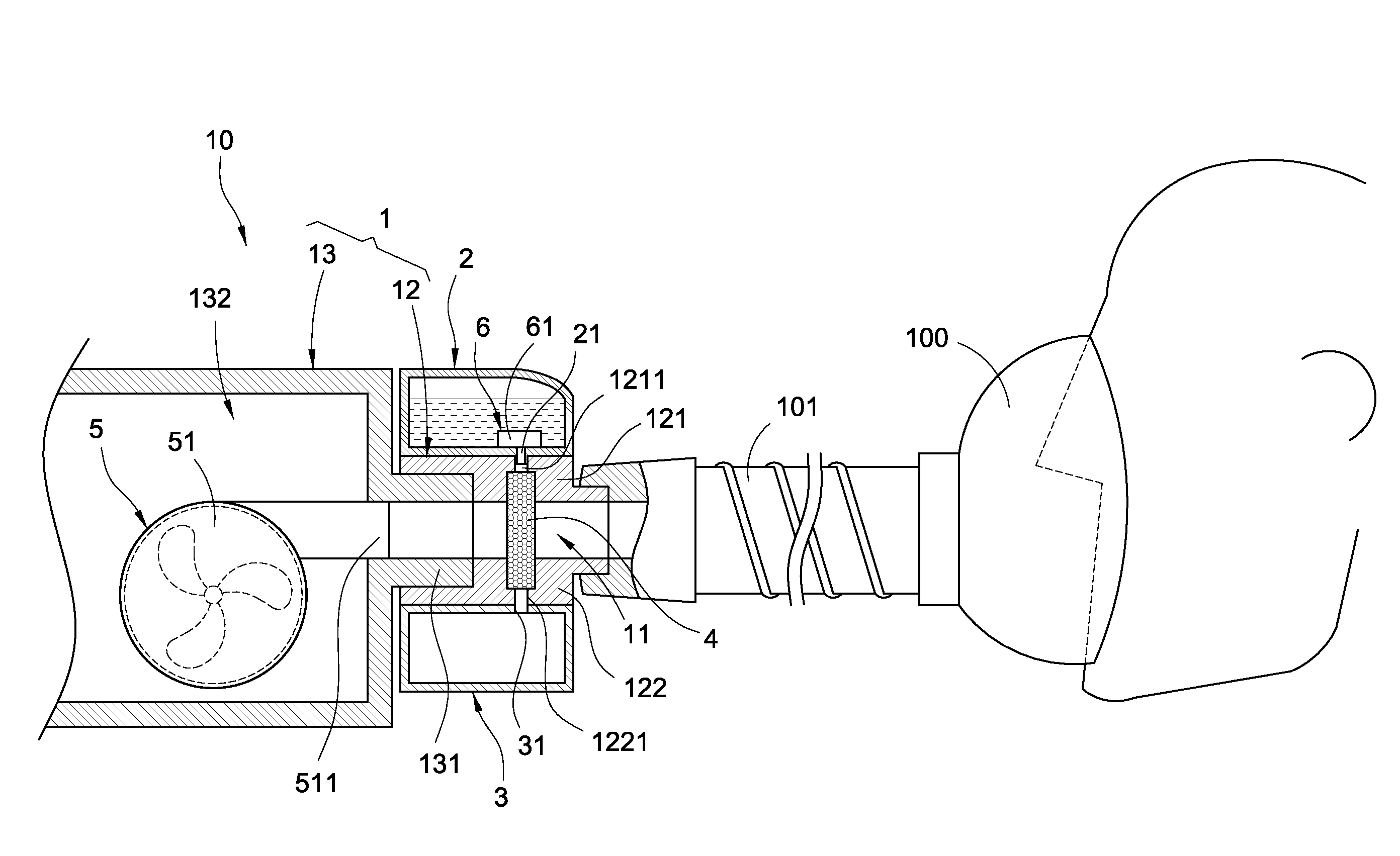
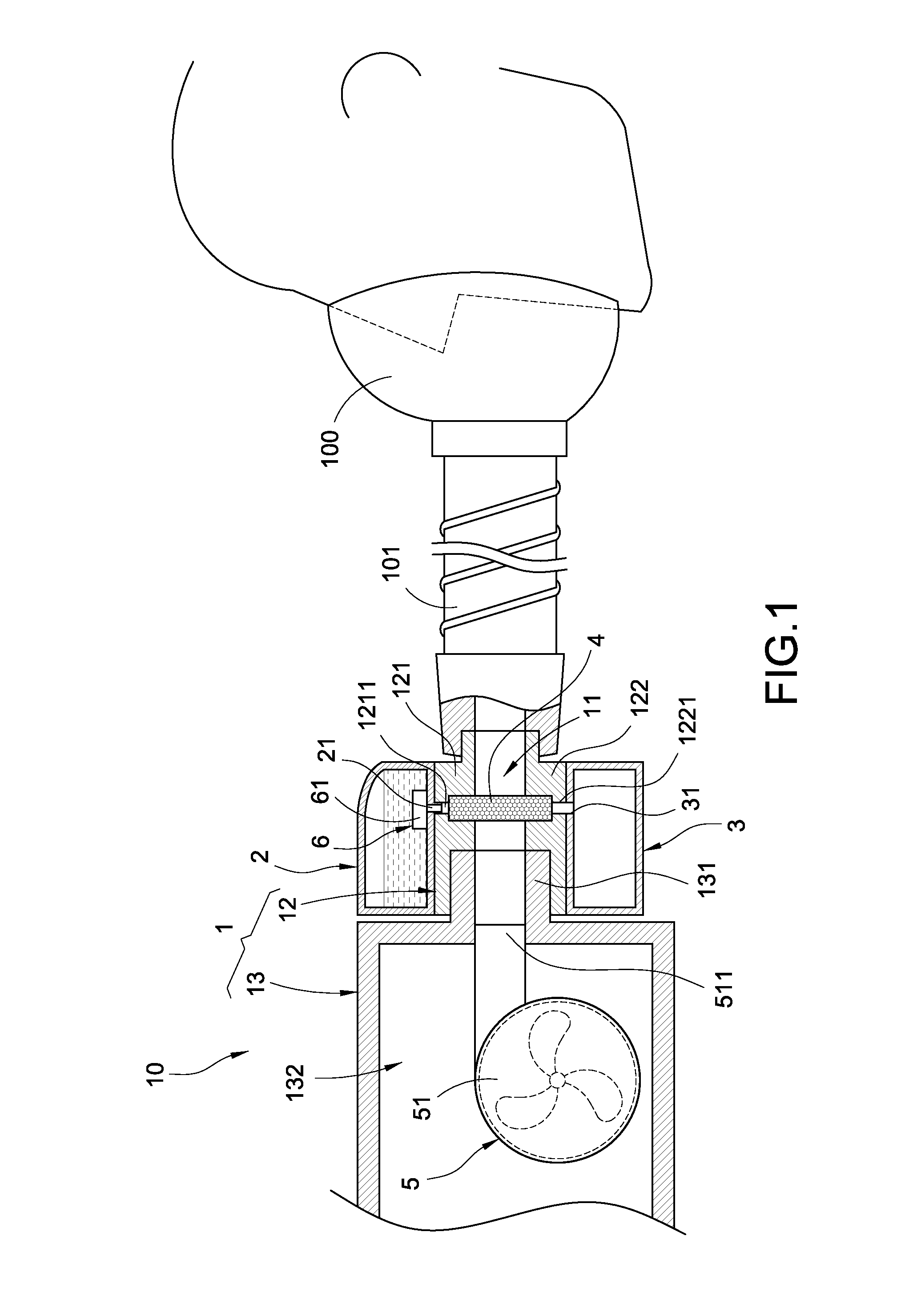
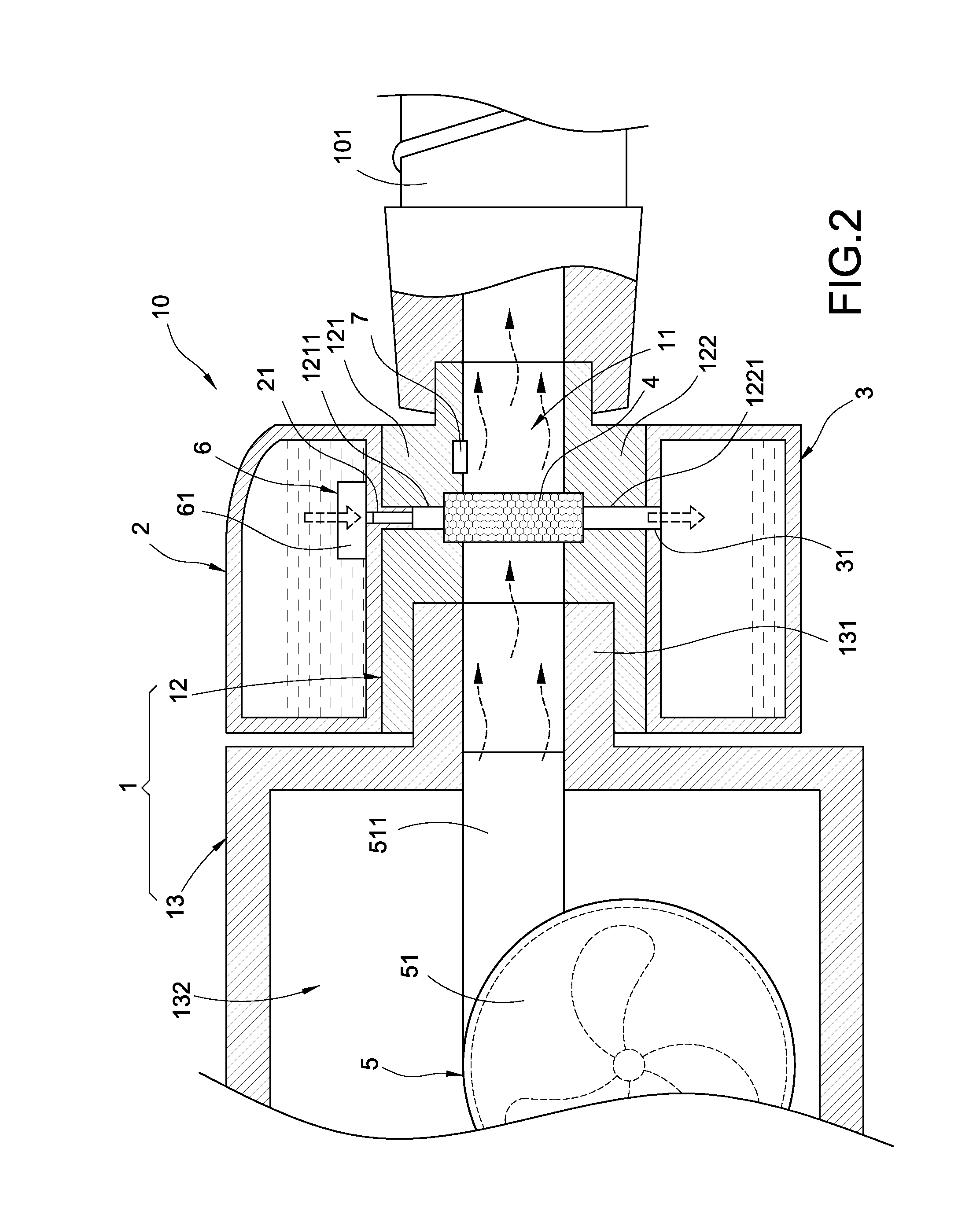
[0023]Please refer to FIGS. 1 and 2 which show a humidifying device for a breathing mask according to the present invention. The breathing mask 100 including a breathing tube 101 assembled thereto. The humidifying device 10 comprises a body 1, a liquid discharger 2, a liquid receiver 3, and a water-absorbent member 4.

[0024]The body 1 includes a connecting tube 12. The connecting tube 12 is connected to the breathing tube 101. The connecting tube 12 includes a passage 11. The passage 11 is connected to the breathing tube 101. The body 1 comprises a connecting tube 12 and an assembly base 13. The connecting tube 12 is assembled between the breathing tube 101 and the assembly base 13, and the passage 11 is formed inside the connecting tube 12.

[0025]To be specific, the connecting tube 12 is a joint. According to a cross-sectional view of the connecting tube 12, the connecting tube 12 includes a top tube wall 121 and a bottom tube wall 122 disposed corresponding to each other. The top tu...

third embodiment

[0047]Referring to FIG. 5, to be specific, the heater 8 is in a block shape, a plate shape, or a webbed shape. According to the present embodiment, the heater 8 is a heating block 82; however, the present invention is not limited thereto. The heating block 82 is disposed in the top through hole 1211, so that the water or therapeutic liquid is heated by the heating block 82 when the water of therapeutic liquid drops into the top through hole 1211 through the liquid inlet 31. Then, the heated water or therapeutic liquid is absorbed by the water-absorbent member 4. The blowing machine 51 outputs airflow, the airflow includes a large amount of warm moist vapor and flows into the breathing tube 101 after the airflow enters the passage 11 and passes the wet water-absorbent member 4, so as to increase the air humidity in the breathing tube 101 and at the same time achieve the same functions and effects as the

[0048]Besides, the conventional humidifying device usually heats the whole water t...


PUM


Abstract

The present invention relates to a humidifying device for a breathing mask. The breathing mask includes a breathing tube assembled thereto. The humidifying device includes a body, a liquid discharger, a liquid receiver, and a water-absorbent member. The body is connected to the breathing tube. The body includes a passage communicating with the breathing tube. The liquid discharger is fixed to the body. The liquid discharger includes a liquid outlet communicating with the passage. The liquid receiver is fixed to the body and is disposed below the liquid discharger. The liquid receiver includes a liquid inlet communicating with the passage. The water-absorbent member consists of a filtering material. The water-absorbent member is accommodated in the passage and disposed between the liquid outlet and the liquid inlet.

Description

BACKGROUND[0001]1. Technical Field[0002]The present invention relates to a humidifying device and, in particular, to a humidifying device for a breathing mask.[0003]2. Related Art[0004]Breathing masks in the market are mainly used to cover over the mouth and nose of a patient, so as to isolate the mouth and nose from the outside environment. A breathing tube is assembled on the breathing mask. Outside oxygen or therapeutic gas is conveyed into the breathing mask through the breathing tube, so as to provide the oxygen or therapeutic gas to the patient for breathing.[0005]In order to enhance breathing comfort for patients, a breathing tube usually includes a humidifying device to increase humidity of the oxygen or therapeutic gas, thereby preventing breathing discomfort such as thirst.[0006]However, the aforesaid humidifying device has the following defects. First, the conventional humidifying device is too big to carry on. Second, the water tank in the humidifying device contains a g...

Claims


Application Information

Patent Timeline
IPC IPC(8): A61M16/10A61M16/20A61M16/08A61M16/16A61M16/00A61M16/06
CPCA61M16/1095A61M16/0003A61M16/06A61M2205/7527A61M16/161A61M16/201A61M2205/3368A61M16/0875A61M16/164A61M16/1045A61M16/109A61M16/202
Inventor LEE, KUO-LIANGLIN, RUNG-YUNGPAI, SHENG-WEN
Owner DELTA ELECTRONICS INC
Learn More