
Control device for vehicle

a technology for controlling devices and vehicles, applied in electric devices, process and machine control, instruments, etc., can solve the problems of degrading power performance of vehicles and degrading vehicle power performance, and achieve the effect of suppressing the dielectric breakdown of rotating electrical machines and suppressing the degradation of vehicle power performan

Active Publication Date: 2016-03-24
TOYOTA JIDOSHA KK
View PDF4 Cites 1 Cited by
  • Summary
  • Abstract
  • Description
  • Claims
  • Application Information

AI Technical Summary

Benefits of technology

This invention is about a control device for a vehicle that can prevent the motor from overheating and lose power performance. The device prioritizes the change in the gear ratio of the transmission over reducing the voltage to the motor, which prevents damage to the motor and maintains the vehicle's power performance.

Problems solved by technology

However, if the application voltage to the rotating electrical machine is decreased, since the maximum torque to be generated by the rotating electrical machine is decreased, power performance of the vehicle is degraded.
In particular, under operation conditions in which a great vehicle drive force is required, it is undesirable that power performance of the vehicle is degraded.

Method used


Image

  • Control device for vehicle
  • Control device for vehicle
  • Control device for vehicle

Examples


Embodiment Construction

[0025]Hereinafter, a mode (hereinafter, referred to as an embodiment) for carrying out the invention will be described referring to the drawings.

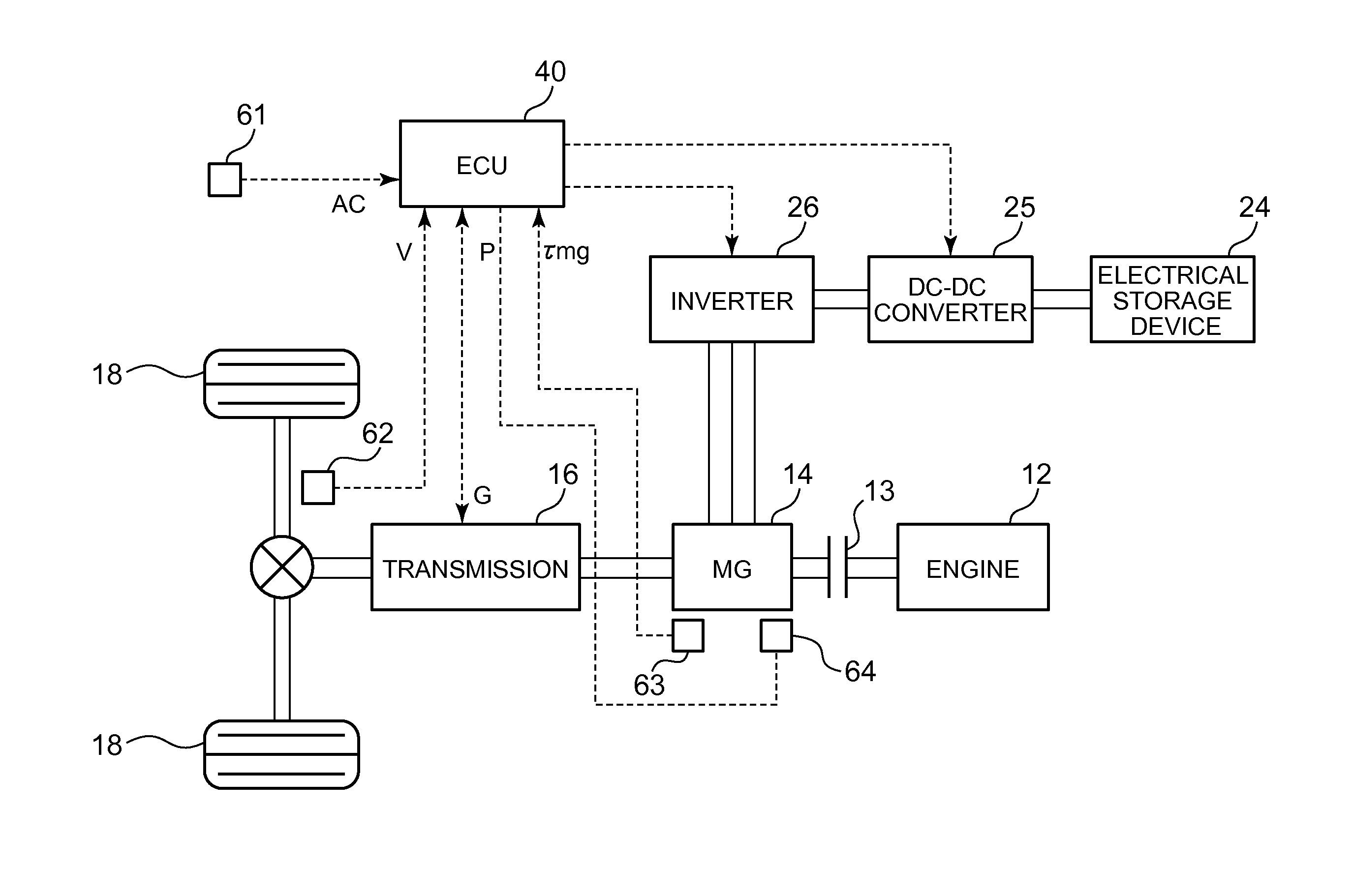
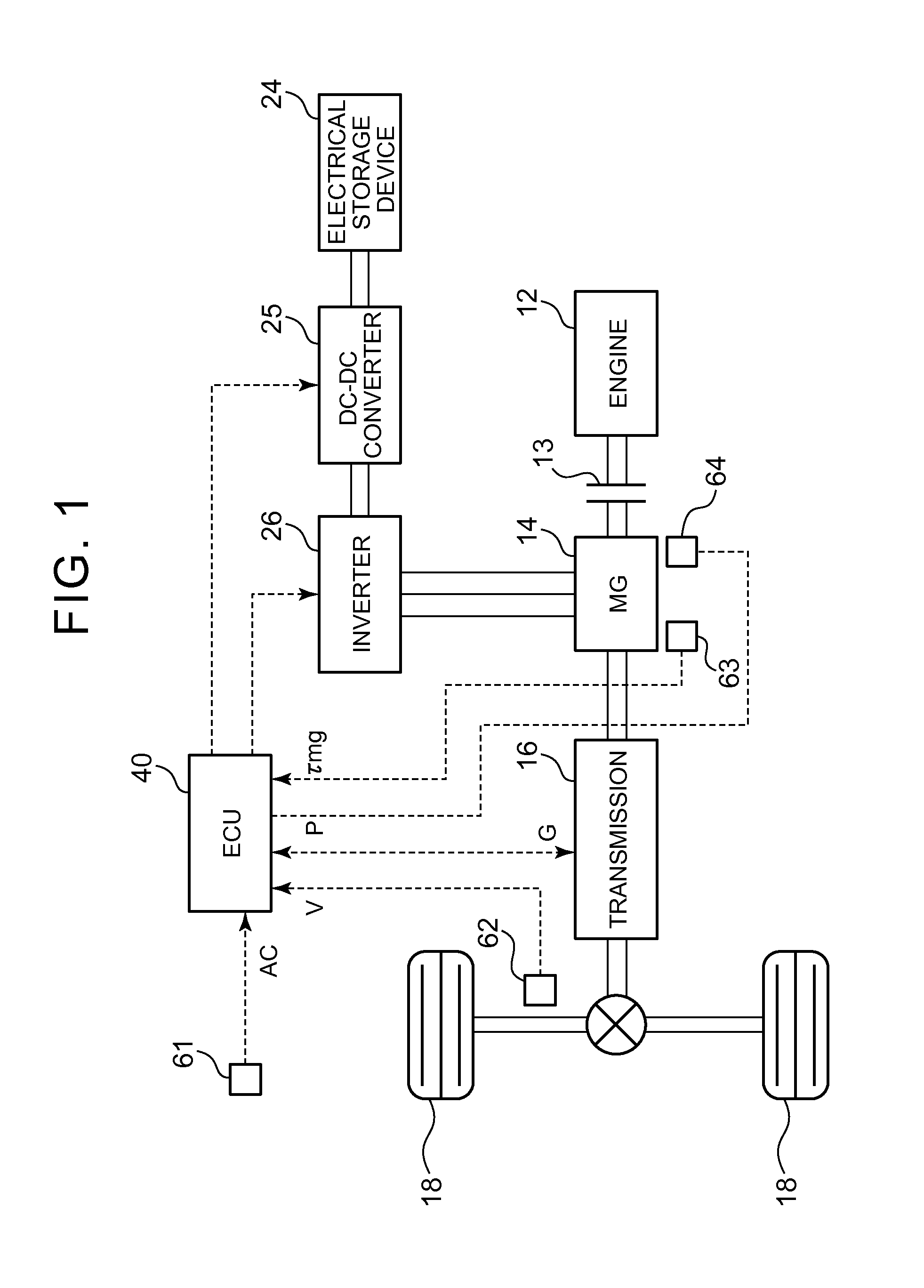
[0026]FIG. 1 is a diagram showing a configuration example of a hybrid vehicle including a control device according to the embodiment of the invention. A clutch 13 is provided between an engine 12 and a motor generator (rotating electrical machine) 14, and the motor generator 14 is coupled to driving wheels 18 through a transmission 16. As the transmission 16, a stepped variable transmission capable of changing a transmission gear ratio G in a stepwise manner can be used. At the time of the engagement of the clutch 13, power generated by the engine 12 can be transmitted to the driving wheels 18 by the shift of the transmission 16, and traveling of the vehicle can be performed using power of the engine 12. In addition, power by powering operation of the motor generator 14 can be transmitted to the driving wheels 18 by the shift of the transmi...


PUM


Abstract

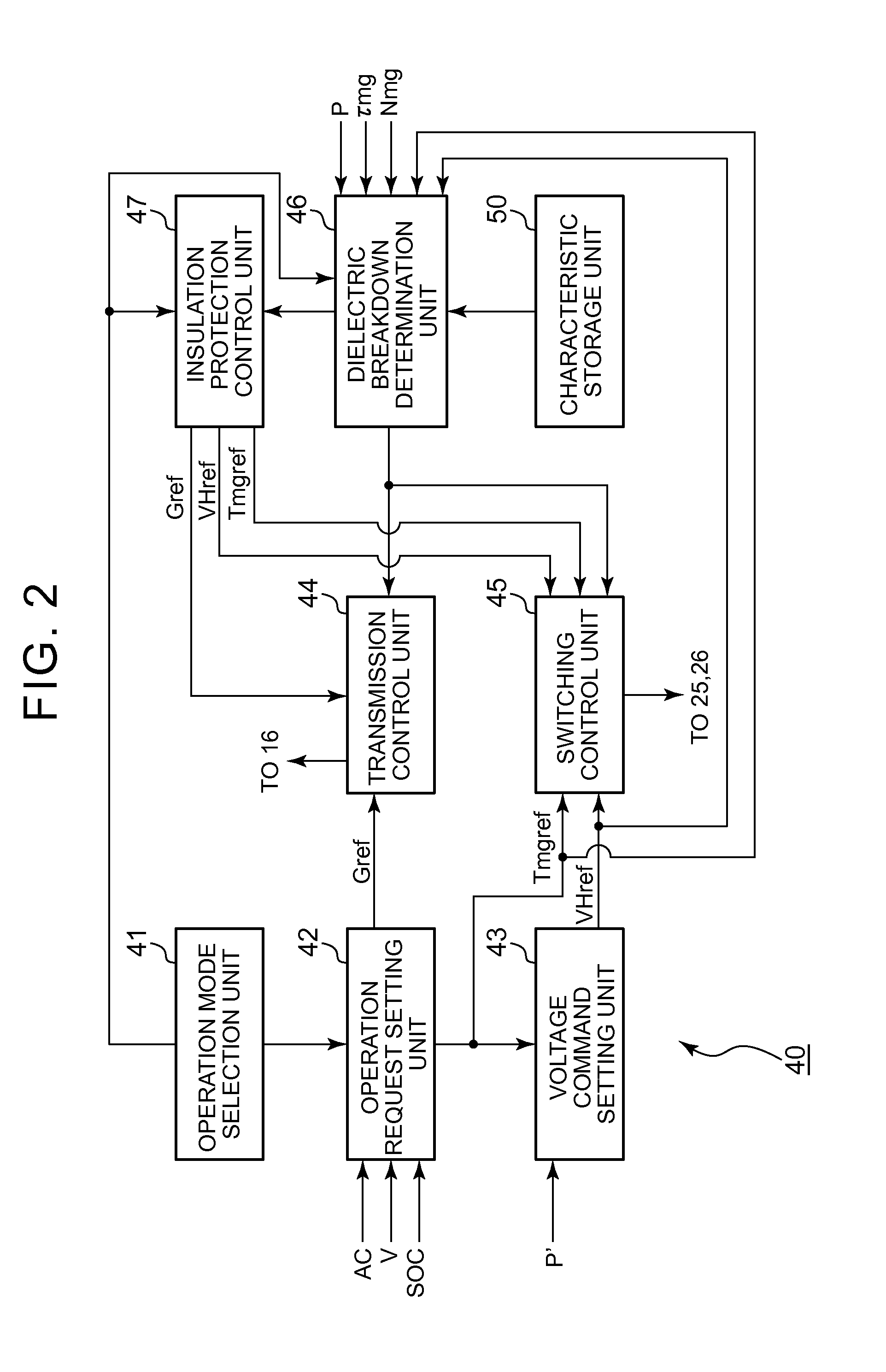
A control device for a vehicle capable of transmitting power of a rotating electrical machine to a driving wheel by a shift of a transmission, includes: an electronic control unit configured to (i) select, as an operation mode of the rotating electrical machine, a normal mode and a power mode in which the rotating electrical machine is operated such that a vehicle drive force is increased more than the normal mode, (ii) execute insulation protection control of the rotating electrical machine when the electronic control unit determines that dielectric breakdown of the rotating electrical machine occurs, and (iii) set a priority of the insulation protection control in an order of a change in a transmission gear ratio of the transmission, a decrease in an application voltage to the rotating electrical machine, and torque limitation of the rotating electrical machine in a state where the power mode is selected.

Description

INCORPORATION BY REFERENCE[0001]The disclosure of Japanese Patent Application No. 2014-194324 filed on Sep. 24, 2014 including the specification, drawings and abstract is incorporated herein by reference in its entirety.BACKGROUND OF THE INVENTION[0002]1. Field of the Invention[0003]The present invention relates to a control device for a vehicle capable of transmitting power of a rotating electrical machine to a driving wheel by the shift of a transmission.[0004]2. Description of Related Art[0005]In Japanese Patent Application Publication No. 2013-62890 (JP 2013-62890 A), when a rotating electrical machine is driven in a region where a surge voltage applied to the rotating electrical machine becomes high, an input voltage to an inverter is decreased, thereby suppressing dielectric breakdown of the rotating electrical machine.[0006]In JP 2013-62890 A, in order to suppress dielectric breakdown of the rotating electrical machine, the application voltage to the rotating electrical machi...

Claims


Application Information

Patent Timeline
IPC IPC(8): B60L3/00B60L3/12B60L15/20B60L50/16
CPCB60L3/0061B60L3/12B60L15/2054B60L2260/167Y02T10/72Y02T10/64Y02T10/62Y02T10/7072
Inventor AOKI, KAZUTAKA
Owner TOYOTA JIDOSHA KK
Learn More