
Inter-Channel Interference Management for Optical Super-Channels

Active Publication Date: 2016-03-17
MITSUBISHI ELECTRIC RES LAB INC
View PDF5 Cites 29 Cited by
  • Summary
  • Abstract
  • Description
  • Claims
  • Application Information

AI Technical Summary

Benefits of technology

The patent describes a method for improving the decoding of signals that are impacted by inter-carrier interference (ICI). The method involves filtering the signal to reduce the ICI and shape the spectrum of the ICI in a way that is advantageous for joint decoding at receivers for each sub-channel. The method also utilizes cooperative super-position coding and information related to the ICI spectrum and signal-to-noise ratio to adaptively adjust coding rates and power arrangements to maximize reliability and data rates. The technical effects of this method include improved signal quality, reduced inter-carrier interference, and improved data transmission reliability.

Problems solved by technology

However, the ICI creates inter-symbol interference (ISI) with frequency offset due to frequency gaps between sub-channels of the optical super-channel.
Furthermore, some embodiments are based on recognition that in some situations the joint decoding of the larger data can limit the data rate of the transmission.

Method used


Image

  • Inter-Channel Interference Management for Optical Super-Channels
  • Inter-Channel Interference Management for Optical Super-Channels
  • Inter-Channel Interference Management for Optical Super-Channels

Examples


Embodiment Construction

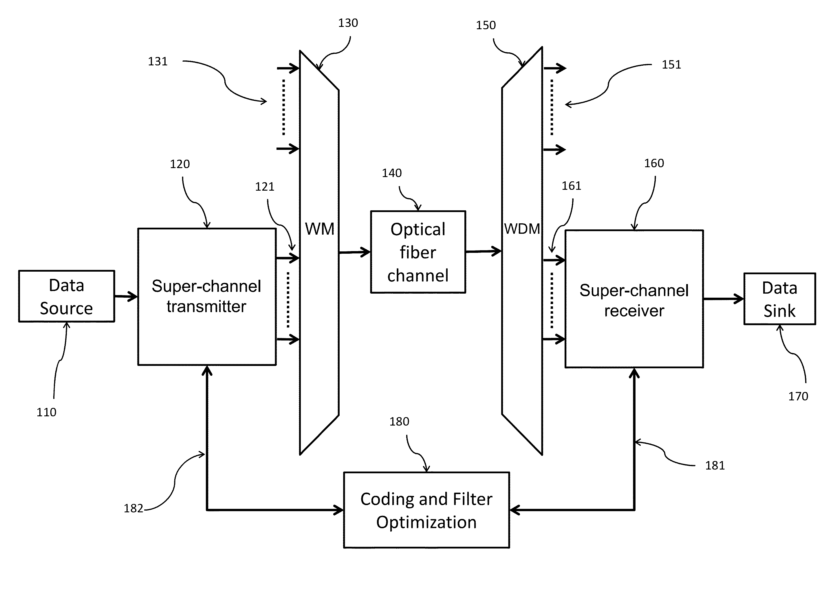
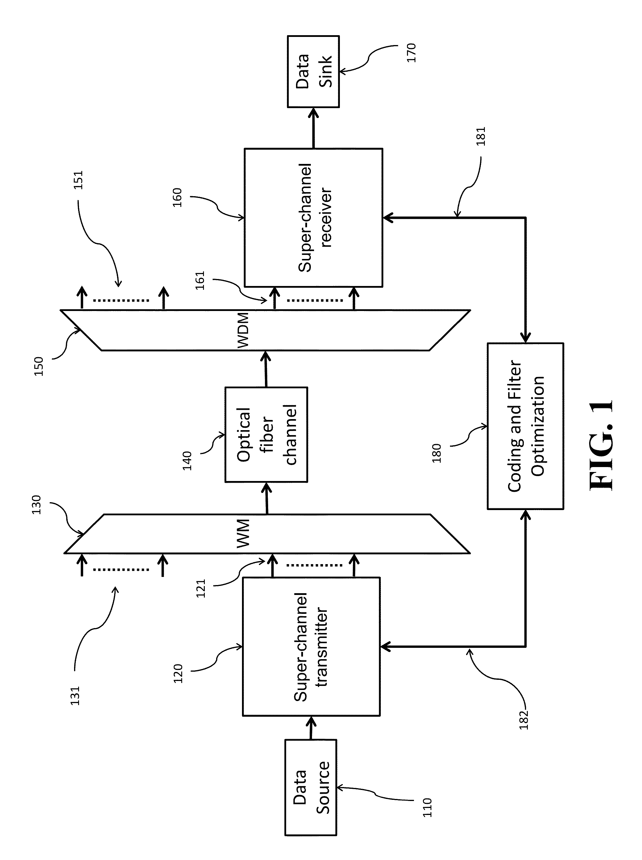
[0027]FIG. 1 shows a block diagram of a super-channel transmission system for transmitting data to a receiver over an optical fiber channel. A sender transmits digital data from data source 110 by a super-channel transmitter 120, which generates a set of data streams to be transmitted over a set of sub-channels of different wavelengths 121. The data streams are combined by an optical wavelength multiplexer (WM) 130, possibly with other independent wavelengths 131 to form an optical signal for transmitting over the optical fiber channel 140.

[0028]On the receiver side, the optical signal is first separated according to multiple wavelengths 151, 161 by an optical wavelength de-multiplexer (WDM) 150. Some of those wavelengths 151 are not related to a super-channel receiver 160. From the other related wavelengths 161, the super-channel receiver 160 recovers the transmitted data 110 to a data sink 170. Some embodiments of the invention use a control block 180 to optimize the super-channel...


PUM


Abstract

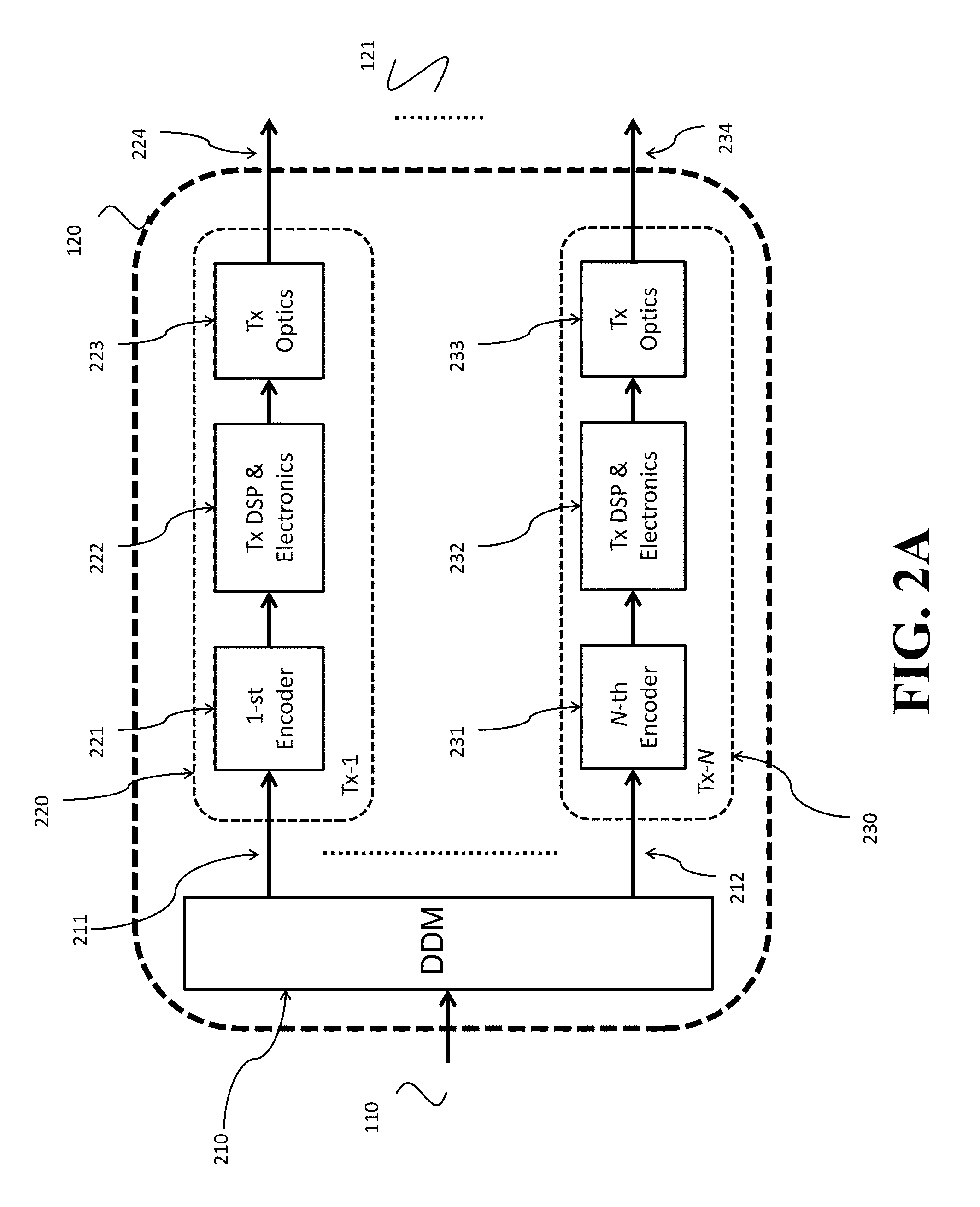
The transmission of data from a transmitter to a receiver over an optical super-channel including a set of sub-channels of different frequencies includes partitioning the data into a set of data streams including one data stream for each sub-channel and partitioning each data stream into a set of sub-streams. Each sub-stream of each data stream is encoded with different forward error correction (FEC) codes to produce a set of encoded sub-streams for each data stream, and the set of encoded sub-streams of each data stream are superimposed with different powers to produce a set of encoded data streams. The set of encoded data streams is multiplexed to produce an optical signal transmitted over the set of sub-channels of the optical super-channel.

Description

FIELD OF THE INVENTION[0001]This invention relates generally to coherent optical communications systems, and more particularly to transmitting data over an optical super-channel.BACKGROUND OF THE INVENTION[0002]Coherent optical communications enable data to be transmitted over long haul optical transmission networks, typically greater than 2,000 km, at high data rates. A coherent detector requires that a received phase-modulated optical signal is digitized. Digitizing the received signal requires a high-speed analog-to-digital converter (ADC). However, an increase in serial ADC sampling rates is difficult to implement for single-wavelength coherent detection at data rates greater than 100 Gbit / s.[0003]A super-channel transmission technique is an evolution in dense wavelength division multiplexing (DWDM), in which multiple optical carriers are combined on a single super-channel to realize a higher data rate in total, and is brought into service in a single operational cycle. Rather t...

Claims


Application Information

Patent Timeline
IPC IPC(8): H04B10/50H04B10/25H04J14/02H04L1/00
CPCH04B10/50H04J14/02H04L1/0041H04B10/25H04L1/0048H04L25/03343H04L25/03821H04B10/506H04B10/2507H04B10/516H03M13/35H03M13/6331H03M13/6343H04B10/25891
Inventor KOIKE-AKINO, TOSHIAKIKOJIMA, KEISUKEMILLAR, DAVID SPARSONS, KIERAN
Owner MITSUBISHI ELECTRIC RES LAB INC
Learn More