
Actively-switched direct refrigerant battery cooling

a technology battery, which is applied in the direction of batteries, electrical appliances, cell temperature control, etc., can solve the problems of limited performance and lifespan of the battery pack, and achieve the effects of large and/or asymmetrical battery pack designs, limited long-term temperature variance, and extended use of direct refrigerant cooling techniques

Inactive Publication Date: 2016-03-17
GM GLOBAL TECH OPERATIONS LLC
View PDF13 Cites 11 Cited by
  • Summary
  • Abstract
  • Description
  • Claims
  • Application Information

AI Technical Summary

Benefits of technology

The present patent is about a system for managing the temperature of a battery pack, which has multiple rows of battery cells. The system uses refrigerant to cool the battery cells and is controlled by a controller which selectively opens and closes valves to adjust the flow of refrigerant. By doing so, the controller helps to limit the temperature variation between the cells and expands the use of direct refrigerant cooling techniques to large battery designs. This system can ensure that cells in a battery pack degrade at approximately the same rate, increasing the overall performance and lifespan of the battery pack.

Problems solved by technology

As the battery cells are arranged in series, the performance and lifespan of the battery pack is largely limited by the performance of its most degraded battery cells.

Method used


Image

  • Actively-switched direct refrigerant battery cooling
  • Actively-switched direct refrigerant battery cooling
  • Actively-switched direct refrigerant battery cooling

Examples


Embodiment Construction

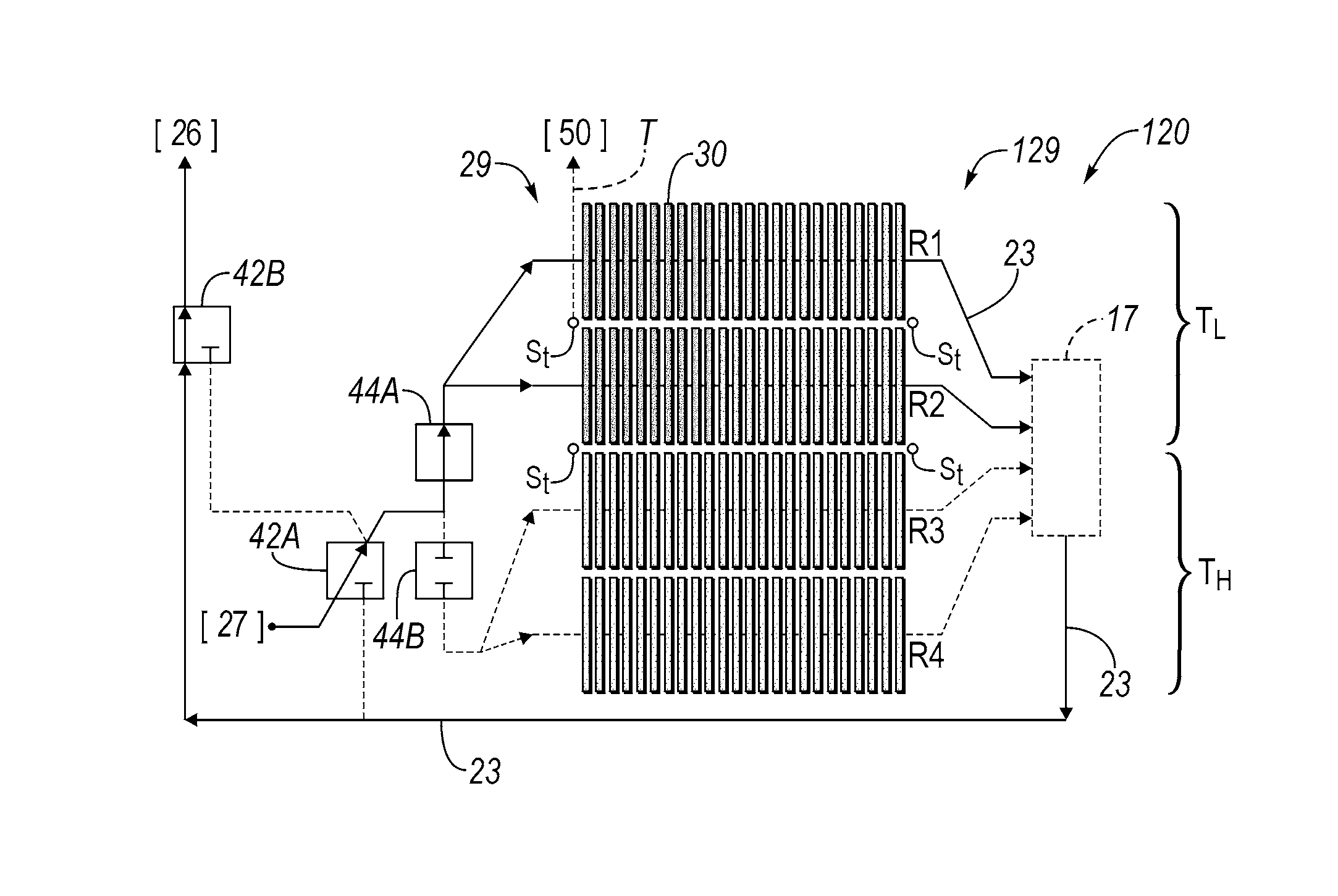
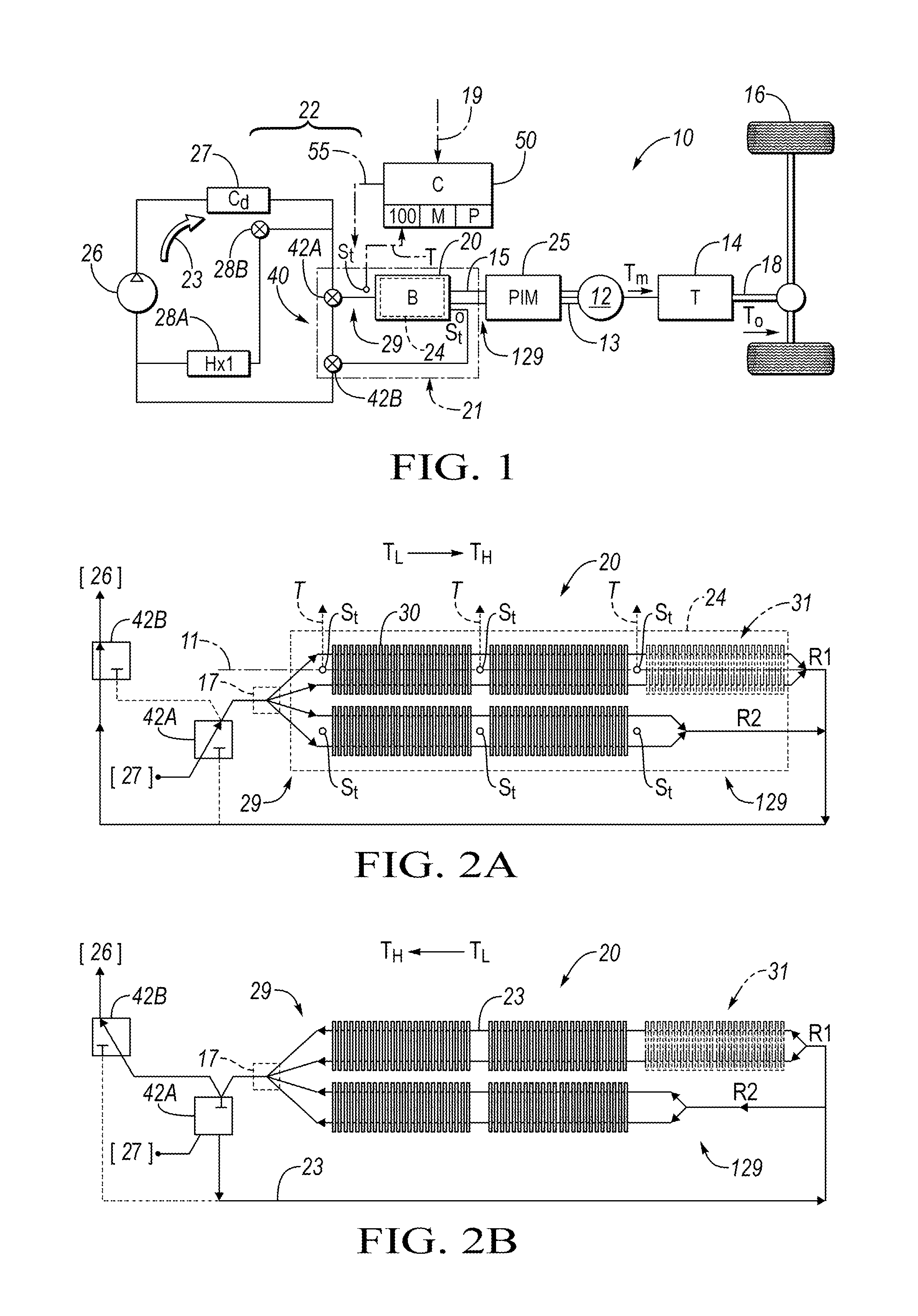
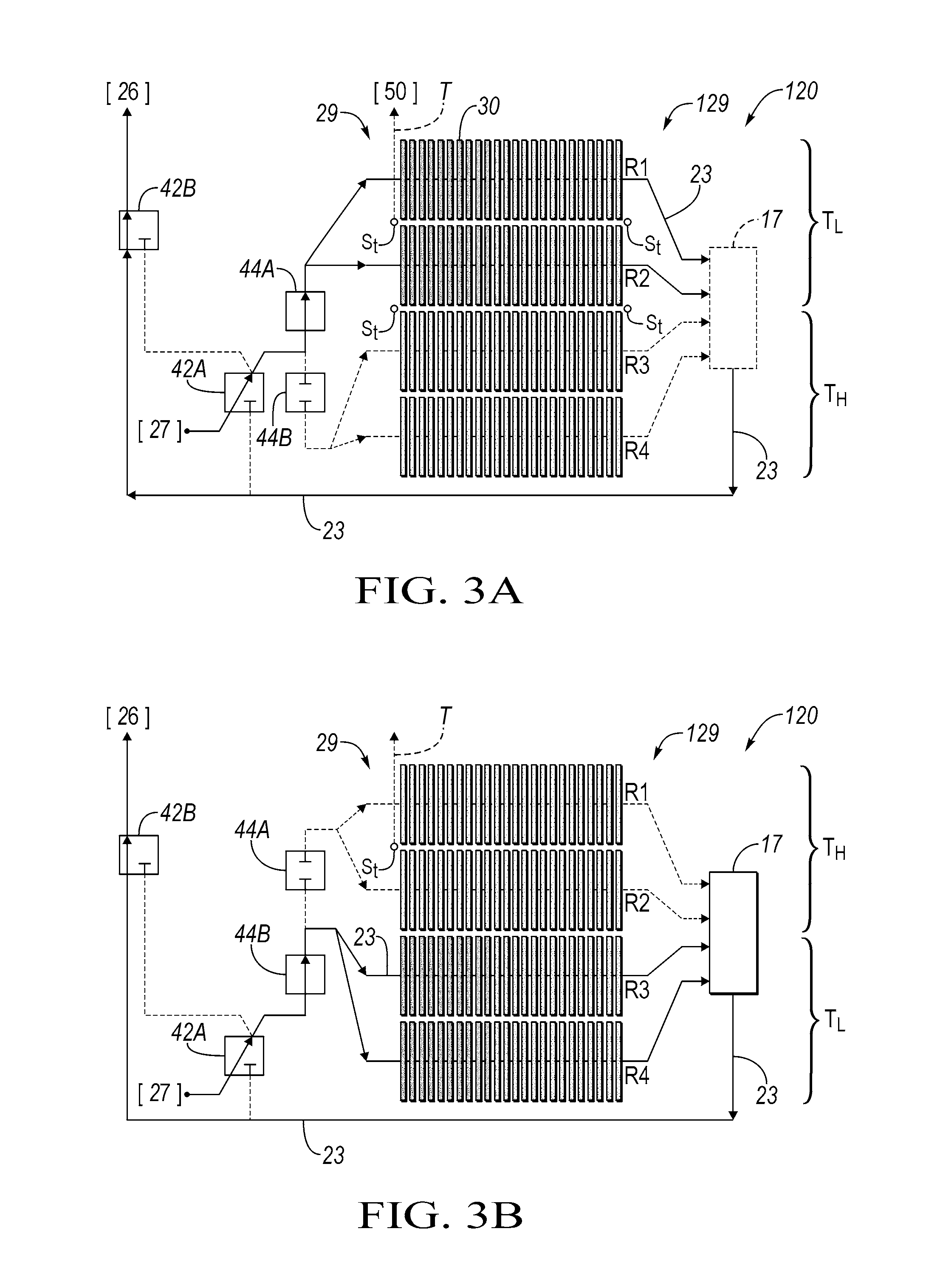
[0017]Referring to the drawings, wherein like reference numerals refer to the same structure throughout the various Figures, an example vehicle 10 is shown schematically in FIG. 1. The vehicle 10 may be embodied variously as a hybrid electric vehicle, an extended-range electric vehicle, a battery electric vehicle, or any other vehicle or other system design having a direct current (DC) battery pack (B) 20 with a plurality of battery cells 30 as best shown in FIGS. 2A-3B. The temperature of the battery pack 20 is regulated via actively-switched direct refrigerant cooling as described in detail below. For simplicity, an internal combustion engine is omitted from the drawings, but could be included in vehicle designs requiring engine torque for any purpose.

[0018]It is recognized herein as a basis of the disclosed design that any of the battery cells 30 located in close proximity to a fluid outlet of a given battery pack, e.g., the example battery pack 20 of FIG. 1, tend to have a relat...


PUM

PropertyMeasurementUnit
conductiveaaaaaaaaaa
temperatureaaaaaaaaaa
concentrationaaaaaaaaaa

Abstract

A thermal management system for a battery pack having a conductive cooling plate and battery cells includes a compressor, flow control valves, temperature sensor(s), and a controller. The compressor circulates refrigerant through the plate to cool the cells. The temperature sensor measures a temperature of the battery pack. The controller is programmed to receive the temperature from the temperature sensors and selectively transmit switching control signals to the valves to command a change in direction or flow of the refrigerant through the cooling plate. This limits a temperature variance between the battery cells over time. A vehicle includes a transmission, an electric traction motor, a battery pack, and the thermal management system noted above. A method includes receiving the temperature, transmitting switching control signals to the valves, and controlling a flow of refrigerant through the plate via the valves in response to the switching control signals.

Description

TECHNICAL FIELD[0001]The present disclosure relates to actively-switched direct refrigerant cooling for a battery.BACKGROUND[0002]Battery electric vehicles, extended range electric vehicles, and strong hybrid electric vehicles are propelled using motor torque from one or more electric traction motors. The motors may draw electrical energy from or deliver a charge to the various battery cells of a rechargeable battery pack depending on the vehicle operating mode. The battery pack may include multiple rows of battery cells that collectively generate a substantial amount of heat during vehicle operation. As a result, thermal management systems are used to help regulate the temperature of the battery pack.[0003]Thermal management systems are typically configured with a fluid pump and a supply of liquid coolant. The fluid pump circulates the coolant through a closed loop of conduit to cool the battery cells and associated power electronics. One or more heat exchangers, condensers, evapor...

Claims


Application Information

Patent Timeline
Patent Type & Authority Applications(United States)
IPC IPC(8): H01M10/625H01M10/613H01M10/6556H01M10/6565
CPCH01M10/625H01M10/613H01M2220/20H01M10/6565H01M10/6556H01M10/617H01M10/63H01M10/6569Y02E60/10
Inventor NEMESH, MARK D.GUERIN, JOHN T.
Owner GM GLOBAL TECH OPERATIONS LLC
Learn More