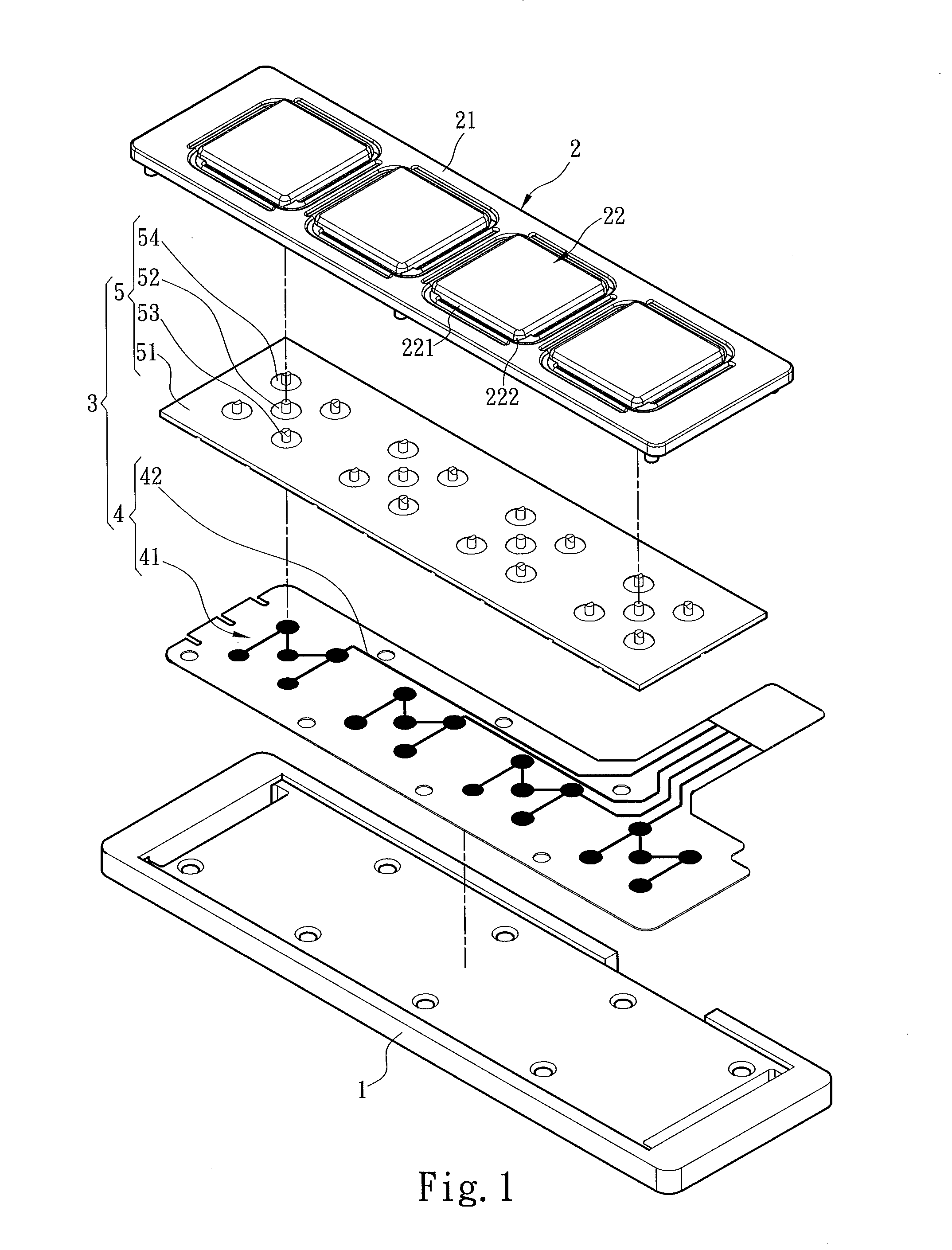
Keyboard equipped with multipoint press positions

a multi-point press, keyboard technology, applied in the field of keyboards, can solve the problems of difficult shrinking of the keyboard size, failure of set-on connection, etc., and achieve the effect of making the keyboard thinner and higher press sensitivity

Inactive Publication Date: 2016-03-17
ZIPPY TECH
View PDF4 Cites 0 Cited by
  • Summary
  • Abstract
  • Description
  • Claims
  • Application Information

AI Technical Summary

Benefits of technology

[0017]1. Through the keycaps and the elastic switches total size of the keyboard can be shrunk as desired, therefore the keyboard can be made thinner and lighter in weight.
[0018]2. With the elastic switches and the trigger switches included in the keyboard, any spot of the keycaps can be pressed to trigger the elastic switches and set on the trigger switches, therefore achieve higher press sensitivity.

Problems solved by technology

In addition, to avoid the keycap from being stricken by the user at two sides rather than in the center and result in tilting and unstable, or unable to trigger the switch, a high sensitive keyboard has been developed in the industry to enable the user to strike the key even on corners and still can trigger the switch.
However, the elastic support rack makes shrinking the size of the keyboard difficult.
If the user lightly touches the corners of the keycap set-on connection could fail.

Method used


Image

  • Keyboard equipped with multipoint press positions
  • Keyboard equipped with multipoint press positions
  • Keyboard equipped with multipoint press positions

Examples


first embodiment

[0037]Please referring to FIGS. 7 through 9, the keycap assembly 2 can be implemented in two types of embodiments. In a first embodiment the support frame 21 includes a plurality of installation apertures 212 defined by a plurality of bracing stems 211 arranged in a staggered manner to hold the keycaps 22. The bracing stems 211 include a plurality of wall surfaces 213 facing the sides 221. The four sides 221 and the wall surfaces 213 are bridged by four movable racks 23 respectively. The four movable racks 23, the keycaps 22 and the bracing stems 211 are integrally formed by injection. Each movable rack 23 has a first stem connecting section 231 connected to any one of the corners 222, and a bracing arm section 233 connected to any one corner 222 via a first bend spot 232 toward another corner 222 to bridge the first stem connecting section 231 and another bracing stem 211. But this is not the limitation of the invention. The bracing arm section 233 is extended parallel against the ...

second embodiment

[0038]Please refer to FIG. 10 for the keycap assembly 2 in which the support frame 21 includes a plurality of installation apertures 212 defined by a plurality of bracing stems 211 arranged in a staggered manner to hold the keycaps 22. The bracing stems 211 include a plurality of wall surfaces 213 facing the sides 221. The four sides 221 and the wall surfaces 213 are bridged by four movable racks 24 respectively. The movable racks 24, the keycaps 22 and the bracing stems 211 are integrally formed by injection. Each movable rack 24 has a first stem connecting section 241, a second stem connecting section 242 and a bracing arm section 243 to bridge the first stem connecting section 241 and the second stem connecting section 242. The first stem connecting section 241 is connected to any one of the corners 222. The bracing arm section 243 is connected to the first stem connecting section 241 between the side 221 and the bracing stem 211 via a first bend spot 244 toward another corner 22...


PUM


Abstract

A keyboard equipped with multipoint press positions comprises at least a baseboard, a keycap assembly and a command trigger assembly. The keycap assembly includes a support frame to hold a plurality of keycaps. The command trigger assembly includes a command circuit board and a plurality of elastic switches. The command circuit board includes a plurality of trigger portions corresponding to the keycaps and triggered by the keycaps, and at least one primary command circuit electrically connected to each trigger portion. The elastic switches are corresponding to and depressible by the keycaps to trigger the trigger portions. Each elastic switch includes a base and a primary movement portion, a first secondary movement portion and a second secondary movement portion that are respectively corresponding to a primary trigger switch and at least two secondary trigger switches of the trigger portions. The keyboard thus formed can provide higher press sensitivity.

Description

FIELD OF THE INVENTION[0001]The present invention relates to a keyboard and particularly to a thin and light keyboard equipped with multipoint press positions to provide multiple points contact.BACKGROUND OF THE INVENTION[0002]With rapid growth of information technology electronic equipments also become very popular. Take the commonly used computers as example, they can be grouped to desktop computers, notebook computers and tablet computers. To increase computer document processing speed most computers are incorporated with a keyboard to facilitate data entry operation of users. The keyboard generally has keycaps and a baseboard. Each keycap and the baseboard are bridged by a key strut. When the keycap is stricken by a user the key strut supports the keycap to form vertical movement against the baseboard. Thus, when the keycap is pressed a switch on the baseboard can be triggered to transmit a reference signal to the processor to output a desired output signal. In addition, to avoi...

Claims


Application Information

Patent Timeline
Patent Type & Authority Applications(United States)
IPC IPC(8): H01H13/80H01H13/14H01H13/20
CPCH01H13/80H01H13/14H01H2203/036H01H2221/088H01H2227/028H01H13/20H01H13/78H01H13/64H01H2217/004H01H2221/044H01H2221/064H01H2225/01H01H2227/034H01H2233/002
Inventor HWA, CHIN-HSIU
Owner ZIPPY TECH
Why Eureka
Try Eureka