
Composite airfoil structures

Active Publication Date: 2016-03-17
GENERAL ELECTRIC CO
View PDF25 Cites 36 Cited by
  • Summary
  • Abstract
  • Description
  • Claims
  • Application Information

AI Technical Summary

Benefits of technology

The patent text describes an airfoil structure and a method for manufacturing it using a composite core made up of fiber bands. The fiber bands are placed at a predetermined position and orientation and interwoven in an in-plane and out-of-plane orientation to form a interleved structure. The method involves disposing layers of prepreg and placing the fiber bands in a predetermined position and orientation to create the composite core. A second set of layers of prepreg is then placed on top of the composite core to form the airfoil structure. The use of fiber placement technology allows for automation and efficiency in manufacturing the airfoil structure. The technical effects include improved strength and durability of the airfoil structure, reduced weight, and improved manufacturing efficiency.

Problems solved by technology

Moreover, when laminated fan blades are subject to high energy impacts (e.g., birds, or other foreign objects), the interlaminar separation can result in delamination and a reduction in the blade's structural integrity.
The shear stresses that may tend to delaminate the blade structure are generated when the composite blade is subjected to high twisting and bending loads.
These loads normally result from impacts which often occur on the leading edge of the blade.
However 3-D woven based blades may have lower stiffness and initial failure strain.

Method used


Image

  • Composite airfoil structures
  • Composite airfoil structures
  • Composite airfoil structures

Examples


Embodiment Construction

[0022]In the following specification and the claims, which follow, reference will be made to a number of terms, which shall be defined to have the following meanings. The singular forms “a”, “an” and “the” include plural referents unless the context clearly dictates otherwise. The terms “comprising,”“including,” and “having” are intended to be inclusive, and mean that there may be additional elements other than the listed elements. The terms “upper”, “lower”, “top”, “bottom”, “first”, “second”, or the like are intended for the purpose of orienting the reader as to specific components parts. “Optional” or “optionally” means that the subsequently described event or circumstance may or may not occur, and that the description includes instances where the event occurs and instances where it does not.

[0023]Approximating language, as used herein throughout the specification and claims, may be applied to modify any quantitative representation that could permissibly vary, without resulting i...


PUM

PropertyMeasurementUnit
Angleaaaaaaaaaa
Angleaaaaaaaaaa
Angleaaaaaaaaaa

Abstract

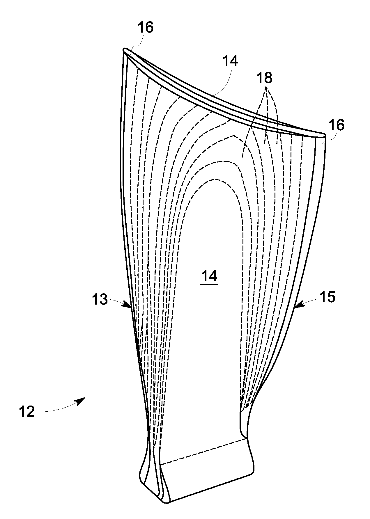
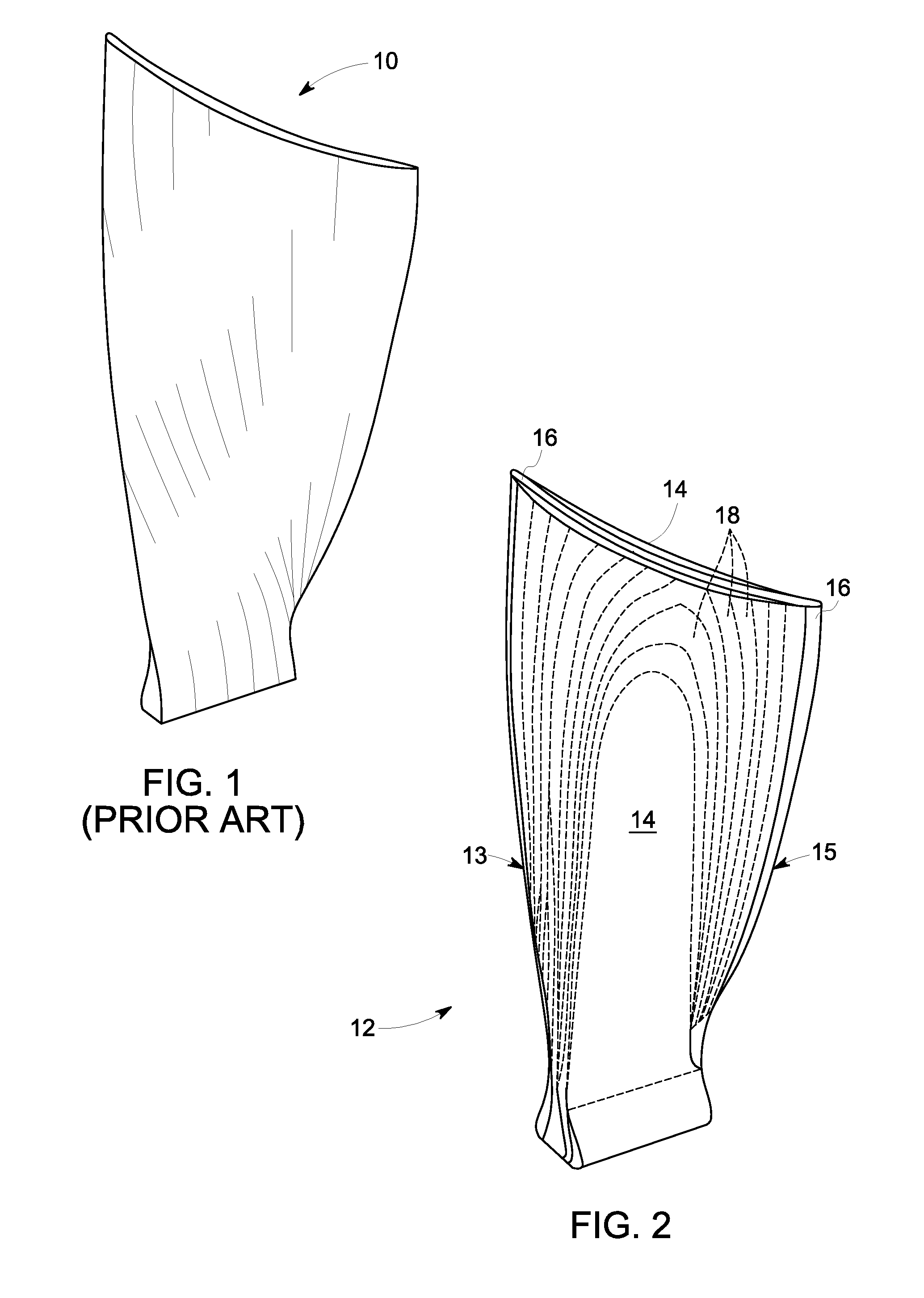
An airfoil structure is presented. The airfoil structure includes an outer casing substantially surrounding a composite core. The composite core includes a plurality of fiber bands, each of the plurality of fiber bands is placed at a predetermined position and orientation at a time, wherein the plurality of fiber bands are interwoven in an in-plane and out-of-plane orientation by interleaving each of the plurality of fiber bands placed in a plane with one or more of the plurality of fiber bands of an adjacent plane to define an interleaved structure. A method for manufacturing an airfoil structure including the composite core is also presented.

Description

BACKGROUND[0001]The present invention relates generally to airfoil structures for turbine engines, and more particularly to airfoil structures including a composite core.[0002]Composite blades developed for commercial aircraft engine fan blades may be constructed of laminated carbon / epoxy “prepreg” material. A “prepreg” is a layer of fibers, for example carbon fibers impregnated with a resin and arranged to form a lamina or a cloth. Prepreg layers may be layered and cured to form a composite structure or laminate. The laminates may experience interlaminar separation under certain circumstances. Moreover, when laminated fan blades are subject to high energy impacts (e.g., birds, or other foreign objects), the interlaminar separation can result in delamination and a reduction in the blade's structural integrity.[0003]The shear stresses that may tend to delaminate the blade structure are generated when the composite blade is subjected to high twisting and bending loads. These loads nor...

Claims


Application Information

Patent Timeline
IPC IPC(8): F04D29/38B29C70/30B29C70/38F04D19/00
CPCF04D29/388F04D19/002B29C70/30B29L2031/08B29K2105/089B29K2063/00B29K2105/0005B29C70/382B29C70/202B29D99/0025F01D5/282F04D29/324F05D2220/36F05D2300/224F05D2300/44F05D2300/6034Y02T50/60
Inventor ANDERSON, TODD ALANKRAY, NICHOLAS JOSEPHGEMEINHARDT, GREGORY CARLSCHNEIDER, MICHAEL HARVEY
Owner GENERAL ELECTRIC CO
Learn More