
Physical quantity sensor element, physical quantity sensor, electronic equipment, and movable body

a technology of physical quantity and sensor element, applied in the direction of acceleration measurement using interia force, instruments, devices using electric/magnetic means, etc., can solve problems such as vibration leakage, and achieve the effect of excellent detection accuracy

Inactive Publication Date: 2016-03-10
COLUMBIA PEAK VENTURES LLC
View PDF3 Cites 2 Cited by
  • Summary
  • Abstract
  • Description
  • Claims
  • Application Information

AI Technical Summary

Benefits of technology

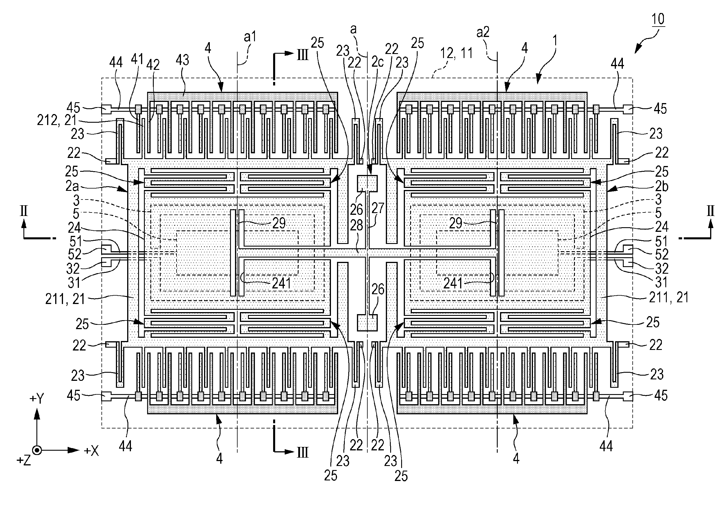
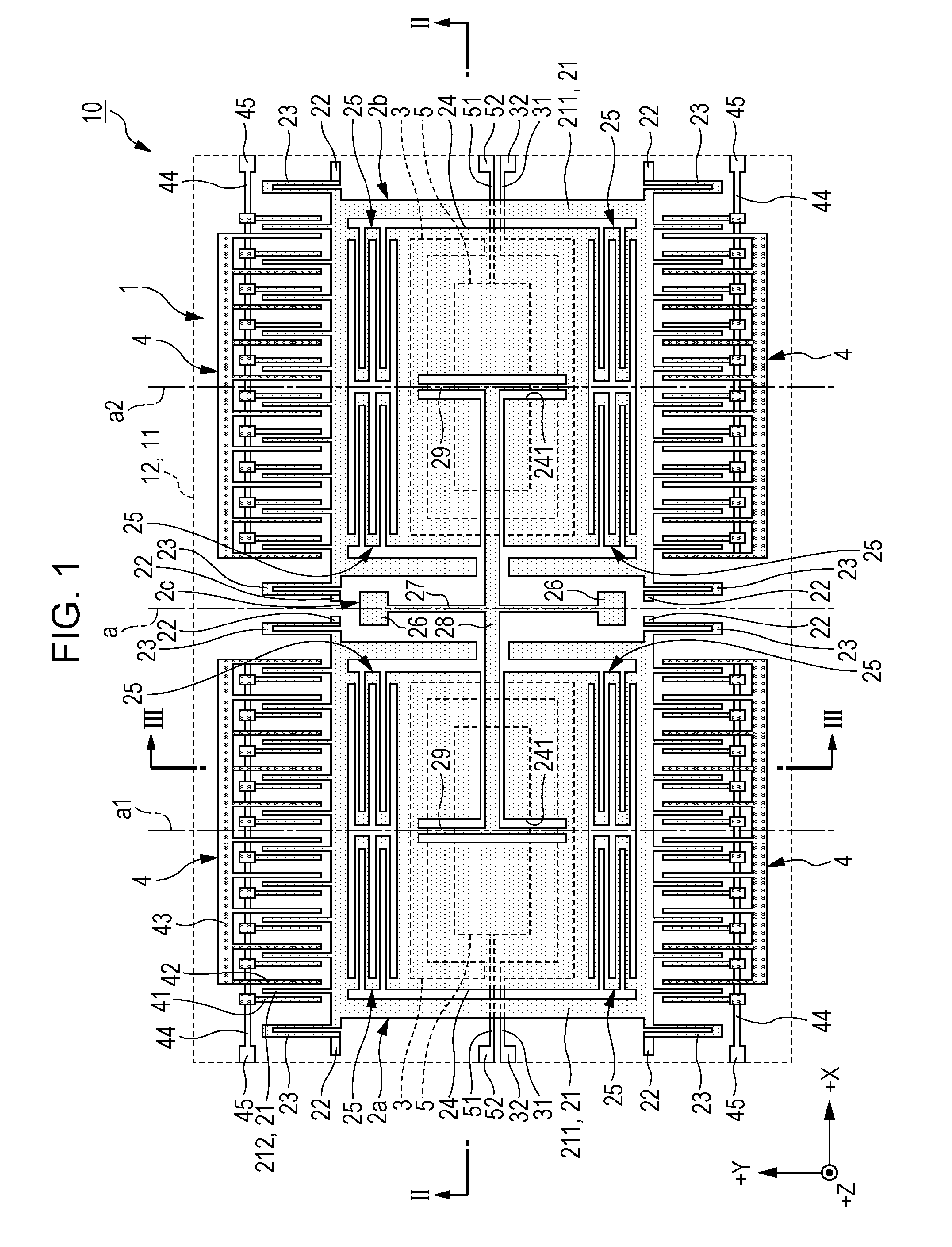
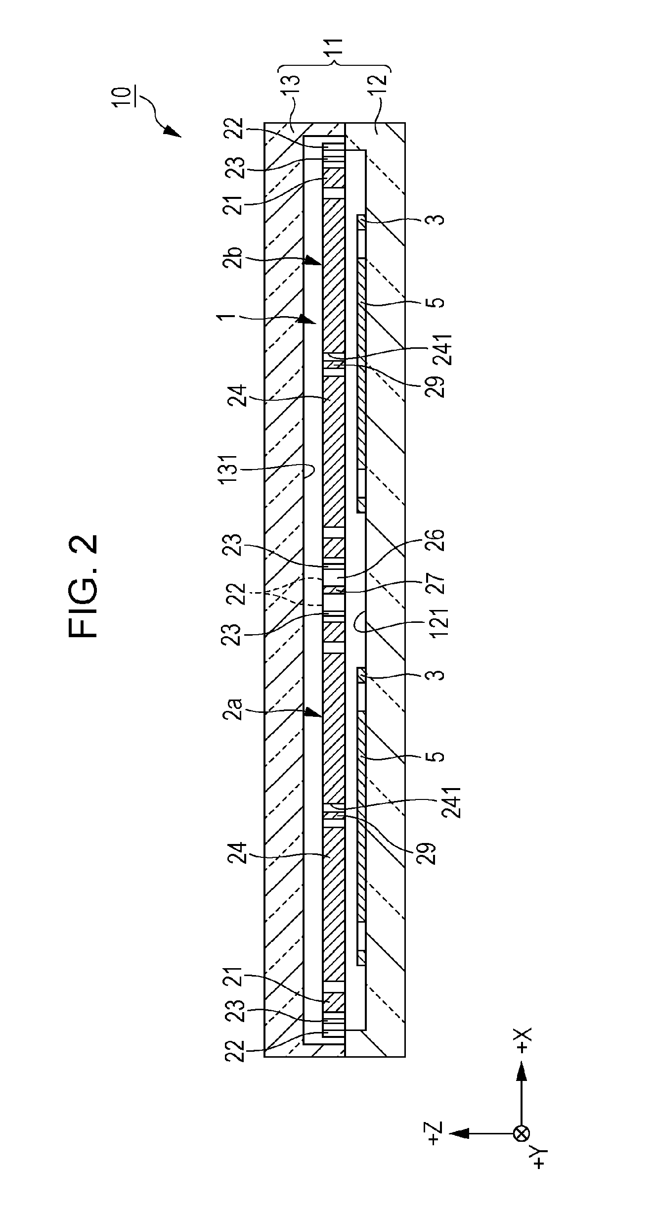
The invention provides a physical quantity sensor element with excellent detection accuracy. The sensor element has a coupling portion that connects two mass portions, which allows stable vibration when an electronic energy is provided. The sensor element has easily deformable portions that reduce the change in its posture, which stabilizes the vibration and reduces the occurrence of vibration leakage. The invention also provides a movable body that includes the physical quantity sensor element. Overall, the invention improves the accuracy of detecting physical quantities.

Problems solved by technology

However, in the angular velocity sensor according to JP-T-2007-509346, end portions of the two mass portions, which are approximated to each other are connected to each other via the link device, and thus the mass portions are inclined to an in-plane direction when driving vibration is performed to an out-plane direction, which results in occurrence of vibration leakage.

Method used


Image

  • Physical quantity sensor element, physical quantity sensor, electronic equipment, and movable body
  • Physical quantity sensor element, physical quantity sensor, electronic equipment, and movable body
  • Physical quantity sensor element, physical quantity sensor, electronic equipment, and movable body

Examples


application example 2

[0011]In the physical quantity sensor element according to the application example, it is preferable that the first easily deformable portion and the second easily deformable portion extend along a direction intersecting with a direction in which the first mass portion and the second mass portion are arranged in planar view seen from a direction along the normal line of the reference surface.

[0012]As such, it is possible to reduce the change of the posture of the first mass portion and the second mass portion with respect to the reference surface by causing the first easily deformable portion and the second easily deformable portion to be twisted. In this way, it is possible to reduce the change of the posture of the first mass portion and the second mass portion with respect to the reference surface with a relatively simple configuration.

application example 3

[0013]In the physical quantity sensor element according to the application example, it is preferable that in planar view seen from a direction along the normal line of the reference surface, a width of each of the first easily deformable portion and the second easily deformable portion is smaller than a width of the coupling portion.

[0014]As such, it is possible to efficiently reduce the change of the posture of the first mass portion and the second mass portion with respect to the reference surface by causing the first easily deformable portion and the second easily deformable portion to be easily twisted. In addition, it is possible to reduce undesirable deformation of the coupling portion and to stabilize the vibration of the first mass portion and the second mass portion.

application example 4

[0015]In the physical quantity sensor element according to the application example, it is preferable that the first mass portion includes a first gap which is disposed in the first easily deformable portion, and the second mass portion includes a second gap portion which is disposed in the second easily deformable portion.

[0016]As such, it is possible to collectively form the first easily deformable portion and the second easily deformable portion with the first mass portion and the second mass portion by processing one substrate.


PUM


Abstract

A physical quantity sensor element of the invention is formed into a plane-shape along an XY plane, and is provided with two driving portions which vibrate in a Z-axis direction, two detecting portions, four beam portions which connect one driving portion and one detecting portion, four beam portions which connect the other detecting portion and the other driving portion, and a coupling portion of which one end is connected to a portion in one of the driving portion and the other end is connected to a portion in the other diving portion in which the each of the deriving portions includes a beam portion which is connected to the end portion of the coupling portion and is deformable so as to reduce a change of a posture of each of the driving portions with respect to an XY plane.

Description

BACKGROUND[0001]1. Technical Field[0002]The present invention relates to a physical quantity sensor element, a physical quantity sensor, electronic equipment, and a movable body.[0003]2. Related Art[0004]Recently, as a physical quantity sensor element using a silicon micro electro mechanical system (MEMS) technology, for example, a capacitance type gyro sensor element (an angular velocity sensor) for detecting angular velocity has been known (for example, refer to JP-T-2007-509346).[0005]For example, an angular velocity sensor according to JP-T-2007-509346 includes two mass portions which are indirectly connected to a frame thereof. The two mass portions are connected via a link device so as to necessarily move to an opposite direction along a Z direction. It is possible to sense the angular velocity of the sensor about a Y-axis by causing the two mass portions to vibrate through a reverse phase in the Z direction, and measuring amplitude of angular vibration which is applied to the...

Claims


Application Information

Patent Timeline
Patent Type & Authority Applications(United States)
IPC IPC(8): G01C19/5705
CPCG01C19/5705G01C19/574
Inventor FURUHATA, MAKOTO
Owner COLUMBIA PEAK VENTURES LLC
Learn More