Dilution gas or air mixer for a combustor of a gas turbine

Active Publication Date: 2016-03-10
ANSALDO ENERGIA SWITZERLAND AG
View PDF11 Cites 6 Cited by
  • Summary
  • Abstract
  • Description
  • Claims
  • Application Information

AI Technical Summary

Benefits of technology

The patent describes a cooling and mixing system for a mixer tube by using injection pipes and similar components. This system helps to improve the mixing quality by avoiding the flow separation and reducing the pulsation and sensitivity to changes in BC. In summary, the patent proposes a more stable combustion by eliminating Strouhal instability through varying tube diameter.

Problems solved by technology

However, this is not sufficient to meet the new requirements.
For injection of a cooling medium from the side walls a high pressure drop is required which is detrimental to the efficiency of a gas turbine operated with such a combustor arrangement and a controlled cooling of the whole flow is difficult.
However, such solution needs longer mixing length and is much more sensitive with respect to changes in the hot gas temperature of the first combustor and dilution air temperature, associated with the change in engine load.

Method used


Image

  • Dilution gas or air mixer for a combustor of a gas turbine
  • Dilution gas or air mixer for a combustor of a gas turbine
  • Dilution gas or air mixer for a combustor of a gas turbine

Examples


Embodiment Construction

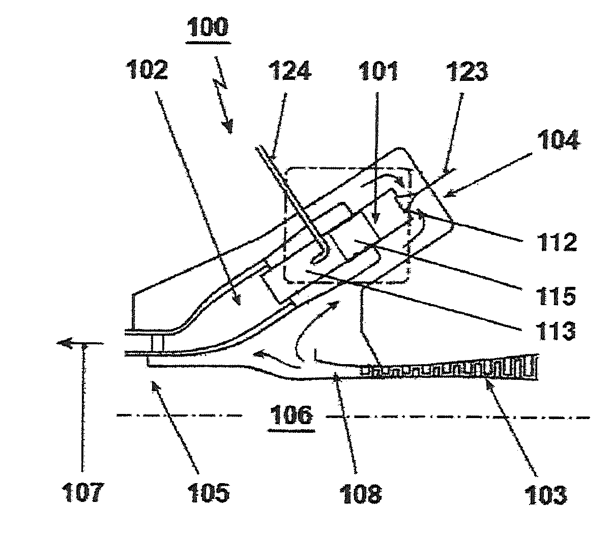
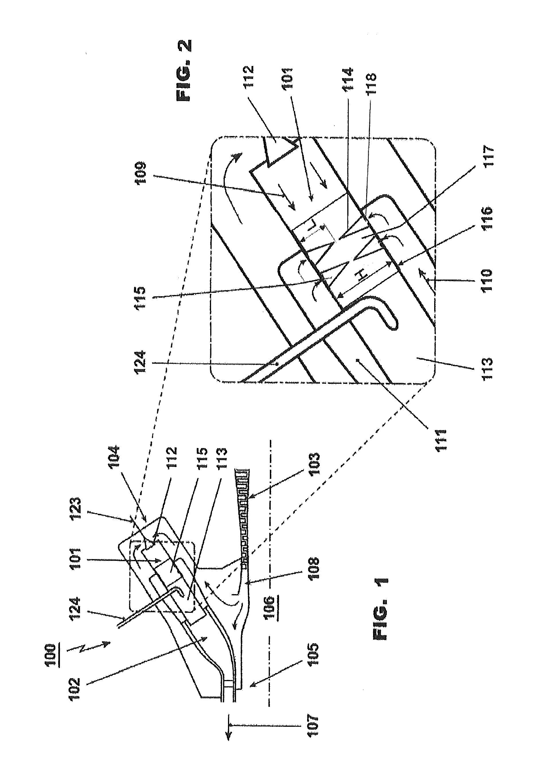
[0109]FIG. 1 shows a gas turbine 100 with a sequential combustor arrangement 104 according to one exemplary embodiment of the invention. It comprises a compressor 103, a combustor arrangement 104, and a turbine 105. The combustor arrangement 104 comprises a first burner 112, a first combustion chamber 101, and a mixer arrangement 117 for admixing a dilution air 110 to the hot gases leaving the first combustion chamber 101 during operation.

[0110]Downstream of the mixer 117 the combustor arrangement 104 further comprises a second burner 113, and a second combustion chamber 102. The first burner 112, first combustion chamber 101, mixer 117, second burner 113 and second combustion chamber 102 are arranged subsequently in a fluid flow direction. Fuel can be introduced into the first burner 112 via a first fuel injection 123, mixed with compressed air which is compressed in the compressor 103, and combusted in the first combustion chamber 101.

[0111]Dilution air 110 (see FIG. 2) is introdu...


PUM


Abstract

The invention referring to a sequential combustor arrangement including a first burner, a first combustion chamber, a mixer arrangement for admixing a dilution air to the hot gases leaving the first combustion chamber during operation, a second burner, and a second combustion chamber arranged sequentially in a fluid flow connection. The mixer is adapted to guide combustion gases in a hot gas flow path extending between the first combustion chamber. The second burner including a duct having an inlet at an upstream end adapted for connection to the first combustion chamber and an outlet at a downstream end adapted for connection to the second burner. The mixer includes at least one group of injection pipes pointing inwards from the side walls of the mixer for admixing the dilution air to cool the hot flue gases leaving the first combustion chamber. The injection pipes are distributed circumferentially along the side wall of the mixer and wherein the injection pipes having a conical or quasi-conical shape addressed to the center of the mixer.

Description

CROSS-REFERENCE TO RELATED APPLICATION[0001]This application claims priority of EP Application No. 14183914.2 filed Sep. 8, 2014, the contents of which are hereby incorporated in its entirety.TECHNICAL FIELD[0002]The invention relates to the technical field of gas turbines with sequential combustion. In particular, the invention refers to a sequential combustor arrangement with a means for admixing dilution gas or air into a hot gas stream.[0003]In addition, the invention refers to a method for operating a gas turbine having means for admixing dilution gas or air into the hot gas stream in a sequential combustor.[0004]Accordingly, this invention refers to a sequential combustor arrangement comprising a first burner, a first combustion chamber, a mixer for admixing a dilution gas or air to the hot gases leaving the first combustion chamber during operation, a second burner, and a second combustion chamber arranged sequentially in a hot gas path of a gas turbine with sequential combus...

Claims


Application Information

Patent Timeline
IPC IPC(8): F23R3/04F02C9/18F23R3/00F23R3/42
CPCF23R3/045F23R3/002F02C9/18F05D2240/40F23R2900/03341F05D2220/32F05D2240/35F23R3/42F23R3/346F02C3/20F23C6/04F23R3/34
Inventor CIANI, ANDREAEROGLU, ADNAN
Owner ANSALDO ENERGIA SWITZERLAND AG
Why Eureka
Try Eureka