Switch assembly of vehicle door latch device

a technology for latching devices and switches, which is applied in the direction of construction fastening devices, electrical locking circuits, lock applications, etc., can solve the problems of increasing the cost of more than one step in the installation operation, and achieve the effect of increasing the cost of more than one step

Active Publication Date: 2016-03-03
MITSUI KINZOKU ACT
View PDF2 Cites 3 Cited by
  • Summary
  • Abstract
  • Description
  • Claims
  • Application Information

AI Technical Summary

Benefits of technology

[0010]According to one aspect of the present invention, there is provided a switch assembly of a vehicle door latch device, the switch assembly including: a latch switch detecting a position of a latch, the latch being pivotally supported by a latch shaft to be engaged with a striker, the latch shaft being mounted on a latch body, the latch body including an advancement passage into which the striker relatively advances upon door closure; a ratchet switch that detecting a position of a ratchet, the ratchet being pivotally supported by a ratchet shaft to be engaged with the latch and prevented reverse rotation of the latch, the ratchet shaft being mounted on the latch body; and a one common switch case that the latch switch and the ratchet switch are installed in the one common switch case, wherein the latch and the ratchet are arranged on a front face side of the latch body, the latch shaft and the ratchet shaft are arranged to be isolated across a striker moving trajectory of the striker, and the common switch case is arranged on the latch body on one side of the striker moving trajectory.
[0011]The switch assembly according to another aspect of the present invention may include a latch switch lever that rotates in association with the latch and includes a cam surface that comes into contact with a movable terminal of the latch switch. The latch switch lever is arranged on the rear face of the latch body, and the movable terminal and the cam surface are configured to come into contact with each other at a position where the movable terminal and the cam surface overlap with a back face side bulged portion of the latch body, the back face side bulged portion zoning the advancement passage.

Problems solved by technology

In a latch unit employing the “reaction force halving structure”, the latch switch L and the ratchet switch M are also respectively arranged separately to the latch side and the ratchet side divided by the advancement passage G, on the rear face side of the latch body A. Accordingly, two switch assemblies thus needing to be separately prepared and more than one step being required in the installation operation have been cost increasing factors.

Method used


Image

  • Switch assembly of vehicle door latch device
  • Switch assembly of vehicle door latch device
  • Switch assembly of vehicle door latch device

Examples


Embodiment Construction

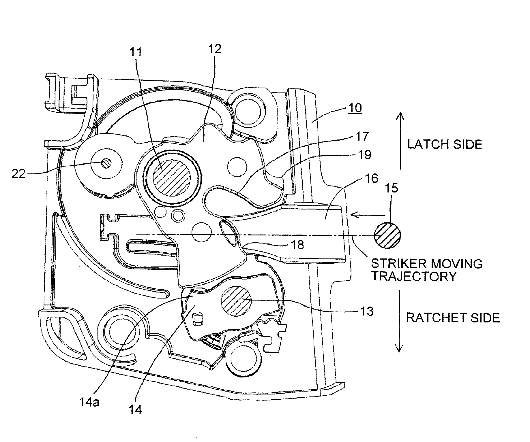
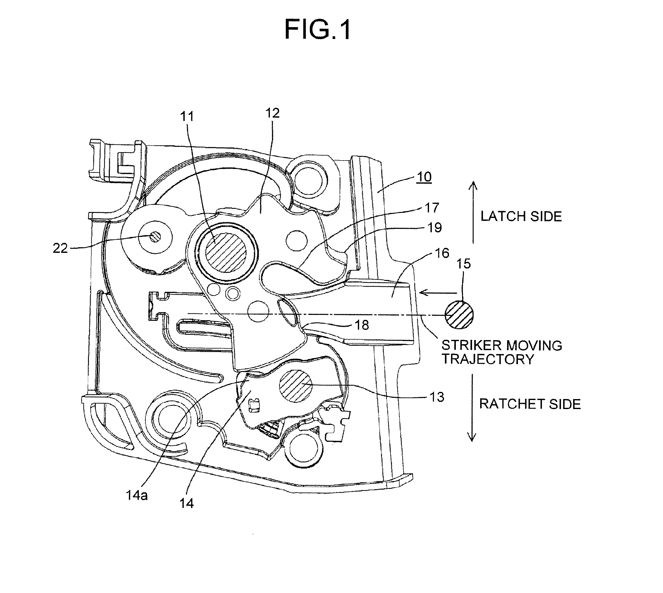
[0022]An embodiment of the present invention will be described. The gist of the present invention is in a switch assembly including a latch switch and a ratchet switch. A configuration of a latch unit itself may be the same as the conventional one. As illustrated in FIG. 1, onto a latch body 10 of the latch unit (latch device), the latch body 10 being formed of a synthetic resin or the like, a latch 12 is pivotally supported by a latch shaft 11 and a ratchet 14 is pivotally supported by a ratchet shaft 13. The latch 12 has an engagement groove 17, a half latch engagement portion 18, and a full latch engagement portion 19. The engagement groove 17 is formed from an outer peripheral surface of the latch 12 towards the latch shaft 11 and has a width that is able to accommodate a striker 15. The half latch engagement portion 18 is formed, as illustrated in FIG. 1, at a portion positioned on a left side of an opening edge portion of the latch 12 in the engagement groove 17. This half lat...


PUM


Abstract

A switch assembly of a vehicle door latch device, the switch assembly includes: a latch switch detecting a position of a latch, the latch being pivotally supported by a latch shaft to be engaged with a striker; a ratchet switch that detecting a position of a ratchet, the ratchet being pivotally supported by a ratchet shaft to be engaged with the latch and prevented reverse rotation of the latch; and a one common switch case that the latch switch and the ratchet switch are installed in the one common switch case. The latch shaft and the ratchet shaft are arranged to be isolated across a striker moving trajectory of the striker. The one common switch case is arranged on a latch body on one side of a striker moving trajectory.

Description

CROSS-REFERENCE TO RELATED APPLICATIONS[0001]The present application claims priority to and incorporates by reference the entire contents of Japanese Patent Application No. 2014-178597 filed in Japan on Sep. 2, 2014.BACKGROUND OF THE INVENTION[0002]1. Field of the Invention[0003]The present invention relates to a vehicle door latch device, and in particular, to a switch assembly that detects positions of a latch and a ratchet of the latch device.[0004]2. Description of the Related Art[0005]FIG. 7 illustrates a front face of a conventionally well known vehicle door latch device (latch unit), and onto a latch body A of the latch device, the latch body A being formed of a synthetic resin or the like, a latch C is pivotally supported by a latch shaft B and a ratchet E is pivotally supported by a ratchet shaft D. When a door moves to be closed, a striker F fixed to the body of the vehicle relatively advances into an advancement passage G formed in the latch body A, engages with an engage...

Claims


Application Information

Patent Timeline
Patent Type & Authority Applications(United States)
IPC IPC(8): E05B85/20
CPCE05B85/20E05B81/20E05B81/14E05B81/66E05B81/68
Inventor HIRAMOTO, SHIGENORI
Owner MITSUI KINZOKU ACT
Why Eureka
Try Eureka