Rain gutter system

a gutter system and rain gutter technology, applied in the direction of roof coverings, roofs, constructions, etc., can solve the problems of damage to the sealing integrity of the roof, inadequate water collection, debris to collect thereon, etc., to reduce the movement of the gutter system, efficiently penetrate the mesh, and efficiently make its course

Active Publication Date: 2016-03-03
MARTIN DANIEL ROBERT
View PDF16 Cites 16 Cited by
  • Summary
  • Abstract
  • Description
  • Claims
  • Application Information

AI Technical Summary

Benefits of technology

The patent text discusses a rain gutter system with a debris cover that helps protect the gutter and building structure from water damage. The gutter is designed with a raised back wall and a drip edge to direct water away from the front wall of the gutter. The debris cover has a fine brim to allow debris to be driven out of the system while still draining water. The system also reduces the movement caused by water flow and allows for efficient water penetration through the gutter system. The debris cover is supported on the gutter and is tilted at an angle to facilitate water collection and debris wash-off. The technical effects of this patent are a more efficient and effective rain gutter system that prevents water damage to buildings and provides better protection against sediment accumulation.

Problems solved by technology

Such systems typically require installation methods that disadvantageously damage the sealing integrity of the roof, fail to address “backflow” affecting the underlying fascia and water collection, and include covers oriented at undesirable slopes and in undesirable designs, causing debris to collect thereon and / or inadequate water collection.
Additionally, the prior art methods of manufacturing gutter systems including gutters, and debris covers with complex cross-sections profile, are complicated and expensive processes, such as methods that uses an extrusion processes, and include heavy, complex, and high maintenance machinery.

Method used


Image

  • Rain gutter system
  • Rain gutter system
  • Rain gutter system

Examples


Embodiment Construction

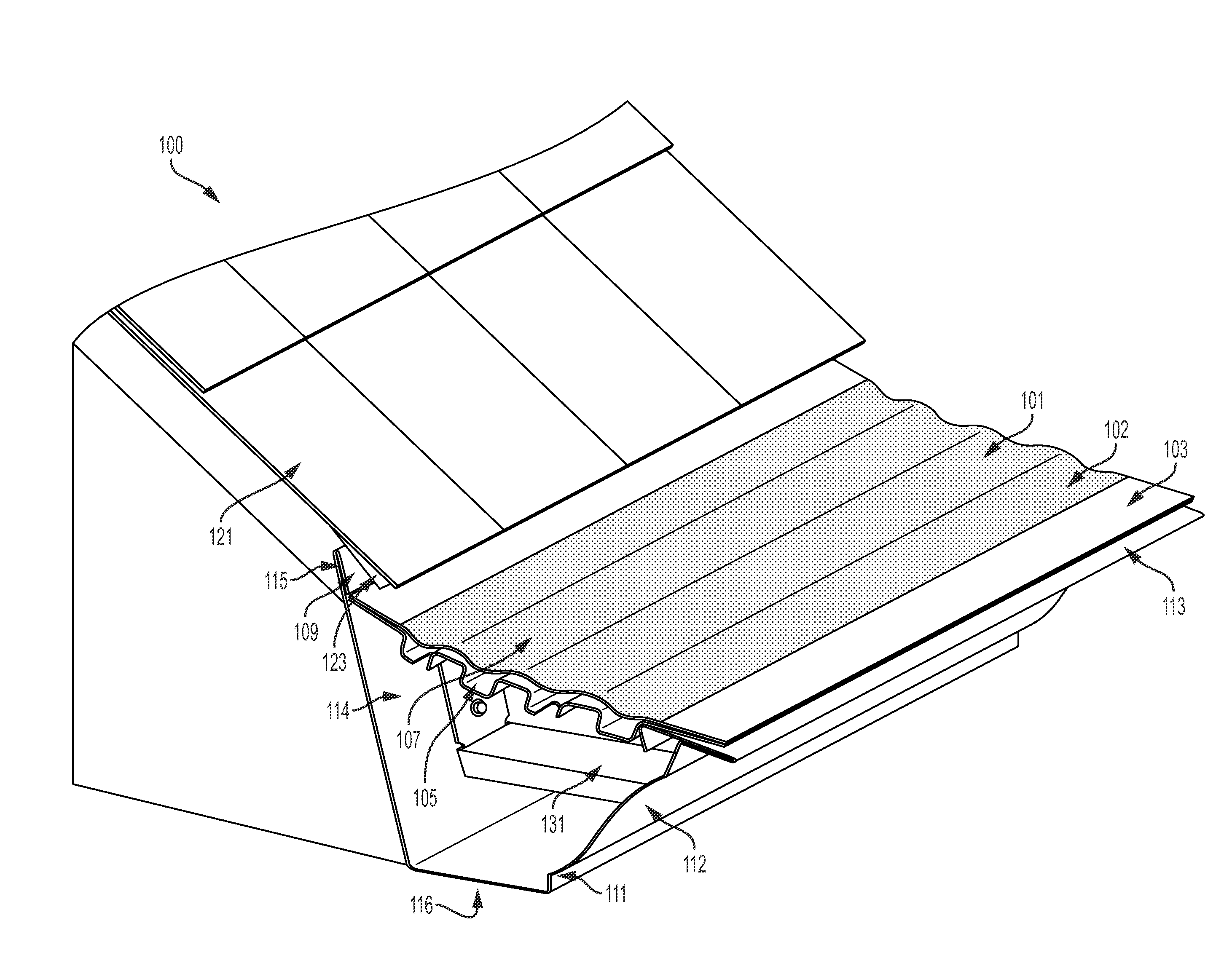
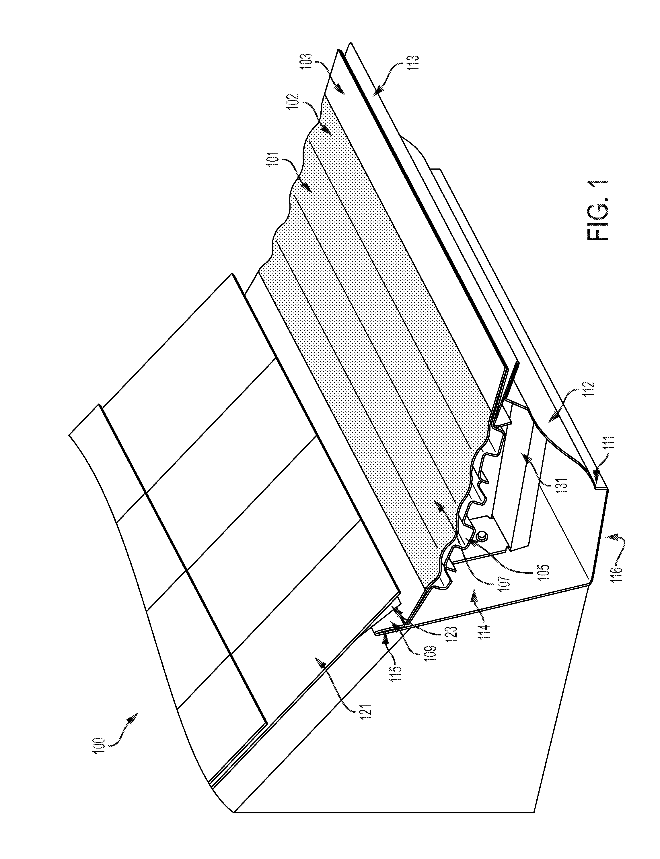
[0050]A preferred rain gutter system, including a gutter, hanger and debris cover, and a method of manufacturing the gutter and the debris cover (panel) are described. In the following description, for the purposes of explanation, numerous specific details are set forth in order to provide a thorough understanding of the preferred embodiments of the invention. It is apparent, however, that the preferred embodiments may be practiced without these specific details or with an equivalent arrangement. In other instances, well-known structures and devices are shown in order to avoid unnecessarily obscuring the preferred embodiments of the invention.

[0051]It is intended that the gutter system provided herein may be installed as original equipment or as a retrofit application, either as a complete system or utilizing parts of the system disclosed herein. For example, in embodiments, the debris panel may be retrofitted to conventional gutter systems. In further embodiments, the debris panel ...


PUM


Abstract

A rain gutter system, including a gutter, and a debris cover, and a method of manufacturing the gutter and the debris cover, wherein the gutter includes a front wall and a back wall interconnected through a bottom and spaced-apart to cooperatively define a water-collecting channel therebetween, the front wall including a lip extending in the direction toward the back wall and a drip edge extending in a direction away from the back wall, the back wall extending upward vertically beyond the height of the front wall. In further embodiments, the rain gutter system includes at least one hanger, and the at least one hanger is positioned in the channel of the gutter, spaced-apart from the bottom. The debris cover allows water to penetrate the debris cover, is attached on top of the gutter at a desirable pitch, and includes a mircomesh.

Description

PRIORITY CLAIM AND CROSS-REFERENCE TO RELATED APPLICATION(S)[0001]The present application claims priority to U.S. Provisional Patent Application Ser. No. 62 / 044,316, filed Aug. 31, 2014, entitled “RAIN GUTTER SYSTEM,” which is incorporated herein by reference in its entirety.BACKGROUND INFORMATION[0002]Conventional gutter systems and gutter covers have been developed in an attempt to collect water while preventing debris from collecting within the gutter. Such systems typically require installation methods that disadvantageously damage the sealing integrity of the roof, fail to address “backflow” affecting the underlying fascia and water collection, and include covers oriented at undesirable slopes and in undesirable designs, causing debris to collect thereon and / or inadequate water collection. Additionally, the prior art methods of manufacturing gutter systems including gutters, and debris covers with complex cross-sections profile, are complicated and expensive processes, such as ...

Claims


Application Information

Patent Timeline
IPC IPC(8): E04D13/076E04D13/064
CPCE04D13/064E04D13/0767E04D13/0643E04D13/0725E04D13/076
Inventor MARTIN, DANIEL, ROBERT
Owner MARTIN DANIEL ROBERT
Why Eureka
Try Eureka