Switched power stage and a method for controlling the latter

a power stage and switch technology, applied in the direction of electric variable regulation, process and machine control, instruments, etc., can solve the problems of sudden rise of the current drawn by the device, voltage overshoot, and inability to compact and integrate a large inductor into a semiconductor chip,

Active Publication Date: 2016-02-18
ENDURA IP HLDG LTD
View PDF6 Cites 13 Cited by
  • Summary
  • Abstract
  • Description
  • Claims
  • Application Information

AI Technical Summary

Benefits of technology

The invention relates to a switching regulator that uses a reference pulse width modulation reference circuitry to regulate the output voltage. The regulator comprises switches for coupling the output inductor to either the supply voltage or ground based on a duty cycle signal, reference switches for coupling the input of a circuit including a reference capacitor, an error amplifier for amplifying the difference between the output of the reference capacitor and the reference voltage, a waveform generator for generating a periodic waveform, and a comparator for comparing the periodic waveform and the output of the error amplifier. The invention also relates to a method of generating a regulated voltage by connecting the output inductor terminal to either the high or low voltage source based on command signals to reduce the difference between the output voltage and the reference voltage. A switched power stage is also provided that comprises an inductor, a switching device, and a control circuit for controlling the switching device based on a high voltage and the output voltage to reduce the difference between the output voltage and the reference voltage.

Problems solved by technology

When one or more circuits of the device are deactivated, the current drawn by the device may drop very shortly, thus resulting in a voltage overshoot if the supplied current does not follow this drop.
Such a big inductor cannot be compact and integrated in a semiconductor chip.
Conversely when a circuit of the powered device is activated, it should be powered on in a very short time, inducing a sudden rise of the current drawn by the device.
This results in subjecting the inductor to conflicting requirements.

Method used


Image

  • Switched power stage and a method for controlling the latter
  • Switched power stage and a method for controlling the latter
  • Switched power stage and a method for controlling the latter

Examples


Embodiment Construction

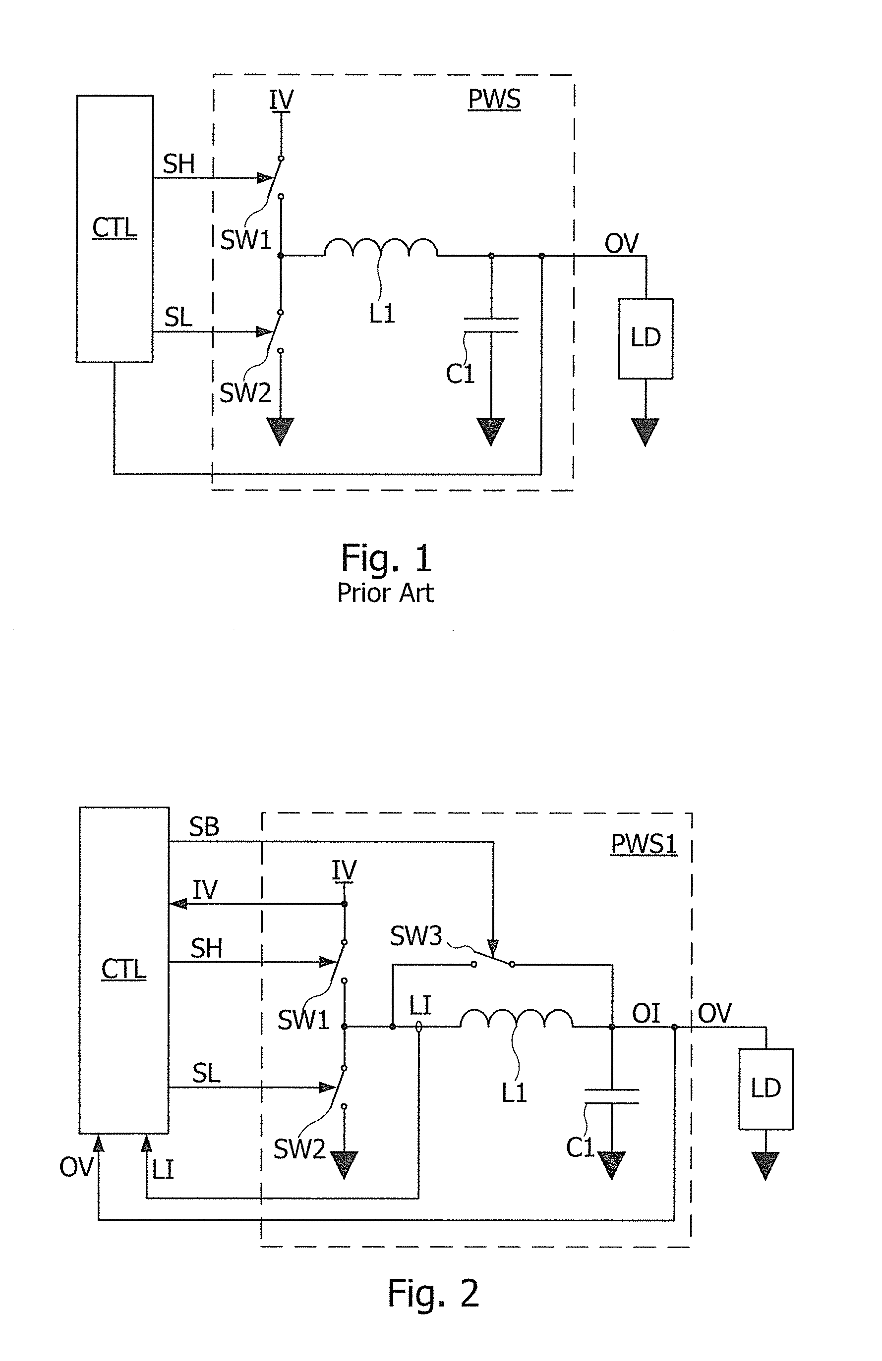
[0031]FIG. 2 is a circuit diagram of a switched power stage according to an embodiment. Referring to FIG. 2, a switched power stage PWS1 of this embodiment, which is a step-down type converter, includes switches SW1, SW2, SW3, an inductor L1, a capacitor C1 and a control circuit CTL controlling the switches SW1, SW2, SW3. A first terminal of the switch SW1 is connected to a voltage source providing a positive input voltage IV. A second terminal of the switch SW1 is connected to a first terminal of the inductor L1, a first terminal of the switch SW2 and a first terminal of the switch SW3. A second terminal of the switch SW2 is connected to a low voltage source, e.g. the ground. A second terminal of the inductor L1 is connected to a second terminal of the switch SW3, and to a first terminal of the capacitor C1, which supplies an output voltage OV to a terminal of a load LD having another terminal connected to the ground. The output voltage OV is lower than the input voltage IV. The se...


PUM


Abstract

The disclosure relates to a method of generating an output voltage, comprising: generating a regulated output voltage from a high voltage source; providing an inductor having a first terminal and a second terminal linked to a low voltage source by a capacitor, the second inductor terminal supplying the output voltage to a load; connecting the first inductor terminal exclusively either to the high voltage source or to the low voltage source or to the second inductor terminal, as a function of command signals to reduce a difference between the output voltage and a reference voltage lower than a high voltage supplied by the high voltage source; and generating a square binary control signal having a duty cycle substantially adjusted to the ratio of the output voltage to the high voltage; the first inductor terminal being connected to the high voltage source or to the low voltage source as a function of a binary state of the control signal.

Description

CROSS REFERENCE TO RELATED APPLICATIONS[0001]This application claims the benefit of the filing date of U.S. Provisional Patent Application No. 62 / 037,063, filed on Aug. 13, 2014, the disclosure of which is incorporated by reference herein.BACKGROUND OF THE INVENTION[0002]The present disclosure generally relates to power stages and voltage converters, and especially to DC-DC converters or switched voltage regulators, capable of varying output voltage and current as a function a processing load of circuits powered by such a converter.[0003]Switched voltage converters are used to convert between differing DC voltages in a wide range of applications. Among switched voltage converters, step-down converters are used to provide a reduced voltage from a higher voltage supply. Typical uses of switched power stages comprise DC-DC converters in particular for battery-operated devices, power stage for class-D amplifiers including audio amplifiers, motor drive circuits, photovoltaic inverters, e...

Claims


Application Information

Patent Timeline
IPC IPC(8): H02M3/156H02M1/08
CPCH02M3/156H02M1/08H02M3/1588H02M3/158Y02B70/10H02M1/0022H02M3/1566
Inventor IHS, HASSANDOSLUOGLU, TANER
Owner ENDURA IP HLDG LTD
Why Eureka
Try Eureka