
Aircraft and methods for operating an aircraft

a technology for aircraft and aircraft, applied in the direction of canard-type aircraft, rotorcraft, vertical landing/take-off aircraft, etc., can solve the problems of limited forward speed, limited operationally to prepared surfaces and facilities requiring large areas of land, and limited maximum speed

Active Publication Date: 2016-02-18
STOPROTOR TECH
View PDF6 Cites 37 Cited by
  • Summary
  • Abstract
  • Description
  • Claims
  • Application Information

AI Technical Summary

Benefits of technology

The patent describes an aircraft that can travel in a way that keeps its rotation axis aligned with the main rotor of a helicopter. The main rotor blades of the helicopter can move independently of each other, and the aircraft can be stabilized in a specific flight profile where the airflow is aligned with the rotor. The technical effect of this design is improved stability and control of the aircraft while traveling in a helicopter's flight profile.

Problems solved by technology

Helicopters are versatile aircraft that are capable of efficient vertical flight from unprepared locations, but they are limited in forward speed.
Aeroplanes can carry large payloads, are capable of high speed, efficient, long range and high altitude flight but are limited operationally to prepared surfaces and facilities requiring large areas of land.
The primary issue with all attempts to convert a rotorcraft (rotary wing aircraft) from rotary wing flight to fixed wing flight with the rotor stopped to act as a fixed wing is the asymmetric lift on the rotor blades generated by the forward motion of the aircraft.
This lift asymmetry results in instability as the rotor is slowed to be stopped.
As any rotary wing aircraft starts to move forward, the asymmetric difference in airflow between the advancing blade and the retreating blade causes imbalances in lift which results in instability.
For conventional helicopters, this asymmetry also limits their maximum speed.
The results of these changes mean a delay in the onset of transonic airflow on the advancing rotor blade and an increase in the margin before blade stall is encountered on the retreating blade, both of which mean the aircraft can fly faster before these issues again become limiting factors.
The advantages of these configurations are outweighed by their design complexity, high total drag and power consumption which are far higher than a comparable fixed wing aircraft.
They are less efficient in the vertical flight role than a helicopter due to their high rotor loading, and are limited to turboprop aircraft speeds in forward flight.
There have also been other design concepts proposed like retractable, foldable and stowed rotors, but none of these have flown successfully.
The major problem encountered by all helicopters and designs attempting to stop or start a rotor system with a radial airflow is asymmetric lift.
As the rotor is slowed, the imbalance between each side starts to increase; eventually the airflow reverses over the full span of the retreating blade.
The instability created by the once per revolution directional change in airflow creates significant instability that has prevented this concept from working successfully.
Although it may be possible for this configuration to perform a conventional takeoff and landing in fixed wing mode, it cannot perform a rolling takeoff or landing in rotary wing modes of operation.
This aircraft proposed the use of large efficient rotors, but this limits the functionality of its fuselage space due to the rotor drive system being inside the fuselage.
As yet there have not been any conventionally designed machines able to stop the rotor in forward flight and then restart it for vertical landing.

Method used


Image

  • Aircraft and methods for operating an aircraft
  • Aircraft and methods for operating an aircraft
  • Aircraft and methods for operating an aircraft

Examples


embodiments

[0224]Reference throughout this specification to “one embodiment” or “an embodiment” means that a particular feature, structure or characteristic described in connection with the embodiment is included in at least one embodiment of the present invention. Thus, appearances of the phrases “in one embodiment” or “in an embodiment” in various places throughout this specification are not necessarily all referring to the same embodiment, but may. Furthermore, the particular features, structures or characteristics may be combined in any suitable manner, as would be apparent to one of ordinary skill in the art from this disclosure, in one or more embodiments.

[0225]Similarly it should be appreciated that in the above description of example embodiments of the invention, various features of the invention are sometimes grouped together in a single embodiment, figure, or description thereof for the purpose of streamlining the disclosure and aiding in the understanding of one or more of the vario...


PUM


Abstract

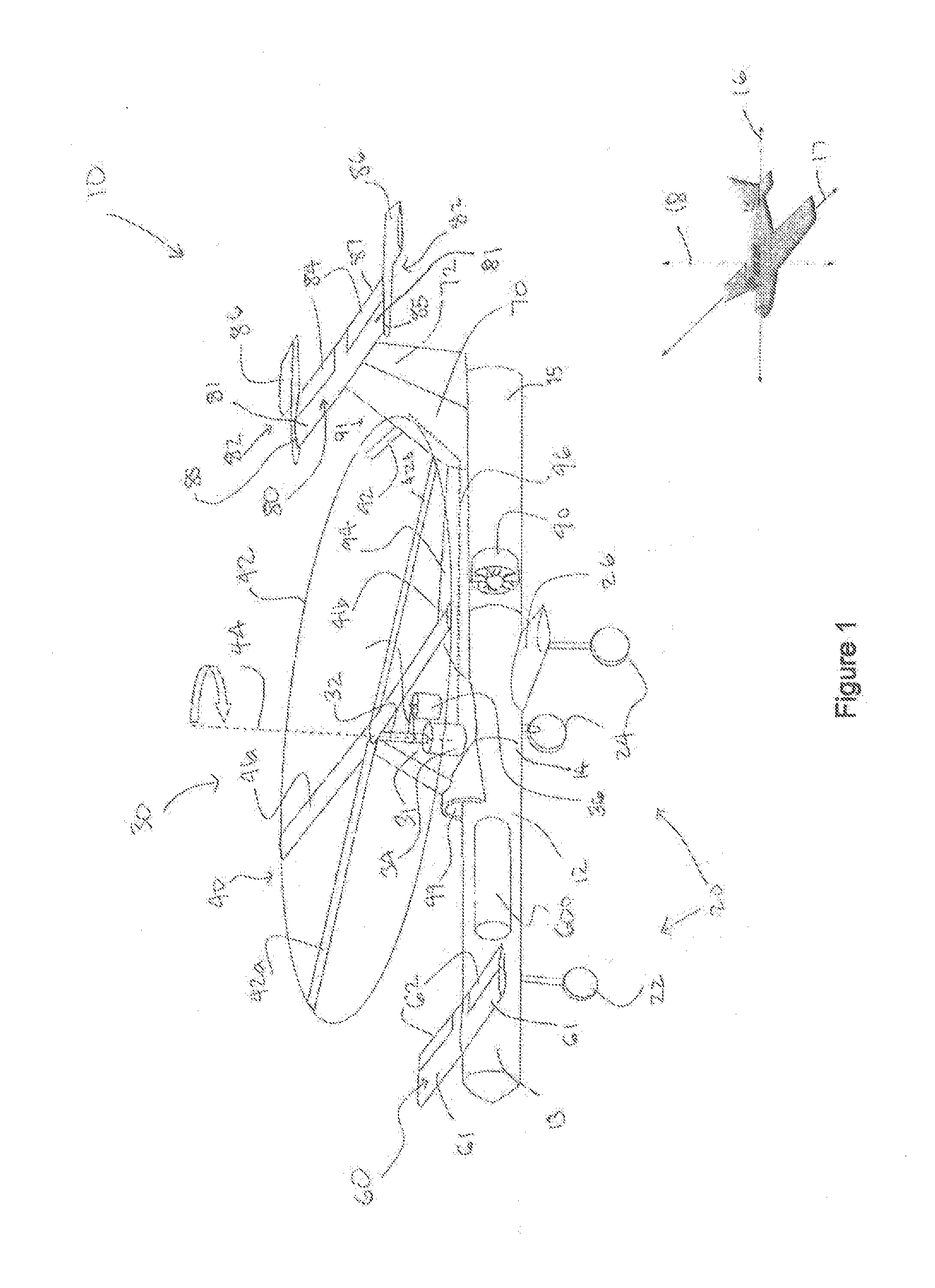
An aircraft (10) comprising a fuselage (12) having a longitudinal axis (16), at least one helicopter main rotor (40) operably mounted to the fuselage (12), the at least one helicopter main rotor (40) comprising rotor blades (41) rotatable about a rotation axis (44), wherein the rotor blades (41) can be stopped in flight and adapted to provide symmetrical wing surfaces relative to the longitudinal axis (16); and the aircraft (10) having at least one control surface (62, 82) operable to provide a relative airflow (306) in flight substantially aligned with the rotation axis (44) of the at least one helicopter main rotor (40).

Description

FIELD OF THE INVENTION[0001]The present invention relates to an aircraft and methods of operating the aircraft.BACKGROUND OF THE INVENTION[0002]The dream of a machine that can take off vertically with the safety and efficiency of a helicopter, transition to wing borne, high speed flight and then return to rotary wing flight for vertical landing, has been around for as long as flight itself.[0003]Helicopters are versatile aircraft that are capable of efficient vertical flight from unprepared locations, but they are limited in forward speed.[0004]Aeroplanes can carry large payloads, are capable of high speed, efficient, long range and high altitude flight but are limited operationally to prepared surfaces and facilities requiring large areas of land.[0005]The attempt to combine these two types of flight has led to many attempts by many inventors since the first aircraft flew in the early 1900's. A lot of advances were made in this field of research during the 1950's and 1960's, the ke...

Claims


Application Information

Patent Timeline
Patent Type & Authority Applications(United States)
IPC IPC(8): B64C27/24B64C5/08B64C9/02B64C27/26B64C29/00
CPCB64C27/24B64C27/26B64C9/02B64C5/08B64C29/0025B64C5/02B64C39/12
Inventor WATKINS, ROWAN, JOHN
Owner STOPROTOR TECH
Learn More