
Methods for simulating the flow of a fluid in a vessel of a nuclear reactor and for calculating the mechanical deformation of assemblies of a nuclear reactor core, and associated computer program products

a technology of nuclear reactor and fluid flow, which is applied in the direction of nuclear power plant control, greenhouse gas reduction, instruments, etc., can solve the problems of inability to reduce the drop time of the core, the risk of local variation of the moderation of the core, and the inability to simulate the flow of the core, so as to improve the computation of the mechanical deformation of the assembly and the flow. the effect of improving the simulation speed and not requiring an excessive amount of computing power

Active Publication Date: 2016-02-11
AREVA NP SAS
View PDF1 Cites 5 Cited by
  • Summary
  • Abstract
  • Description
  • Claims
  • Application Information

AI Technical Summary

Benefits of technology

The invention aims to improve the simulation of fluid flow in a reactor vessel for better modeling of the flow and computation of mechanical deformation of reactor components without requiring excessive computing power.

Problems solved by technology

The deformations of the assemblies are in fact likely to disrupt the operation and performance of the reactor: risk of incomplete insertion of control clusters, which make it possible to adjust the reactivity of the core of the nuclear reactor, or unacceptable increase in their drop time, risk of local variation of the moderation of the core, etc.
During handling, for example during unloading and reloading operations of the core for maintenance, these deformations increase the risks of catching between the fuel assemblies.
However, the simulation of the flow of the fluid inside the vessel is not optimal, homogenous modeling of the core not making it possible to determine the deformations of the fuel assemblies.
Furthermore, this modeling requires an excessive computing power to be able to be implemented with the current computation means.

Method used


Image

  • Methods for simulating the flow of a fluid in a vessel of a nuclear reactor and for calculating the mechanical deformation of assemblies of a nuclear reactor core, and associated computer program products
  • Methods for simulating the flow of a fluid in a vessel of a nuclear reactor and for calculating the mechanical deformation of assemblies of a nuclear reactor core, and associated computer program products
  • Methods for simulating the flow of a fluid in a vessel of a nuclear reactor and for calculating the mechanical deformation of assemblies of a nuclear reactor core, and associated computer program products

Examples


Embodiment Construction

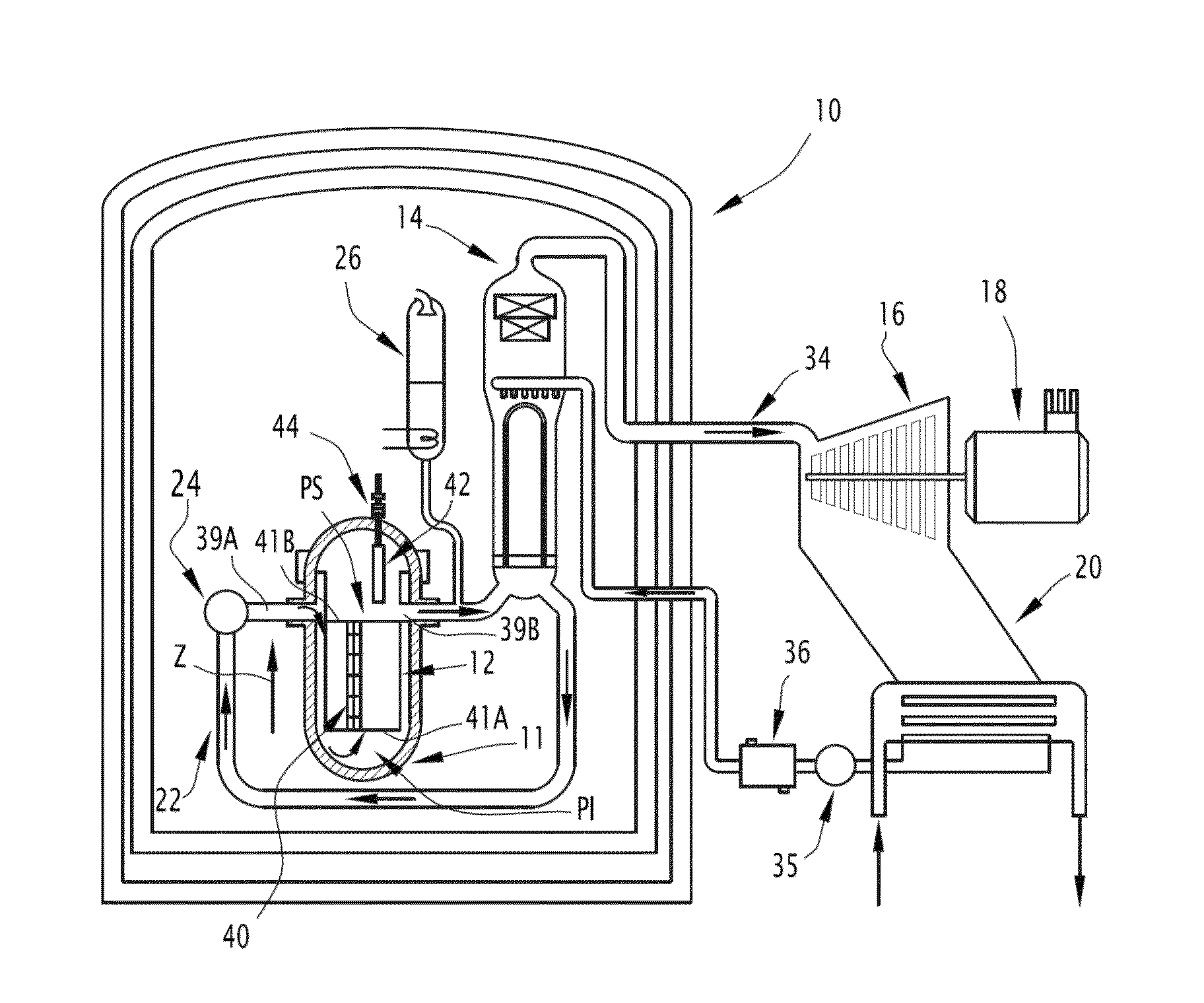
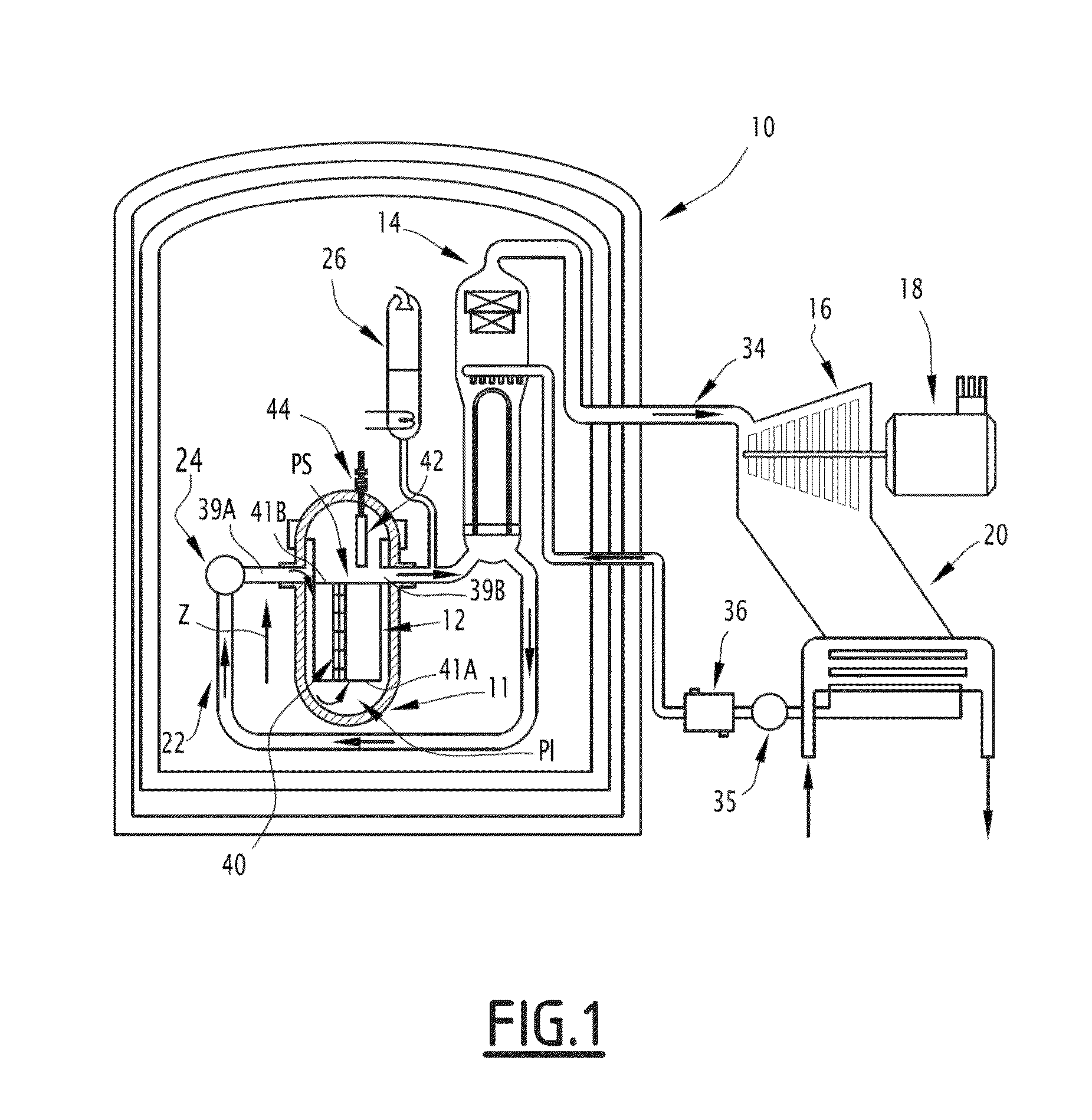
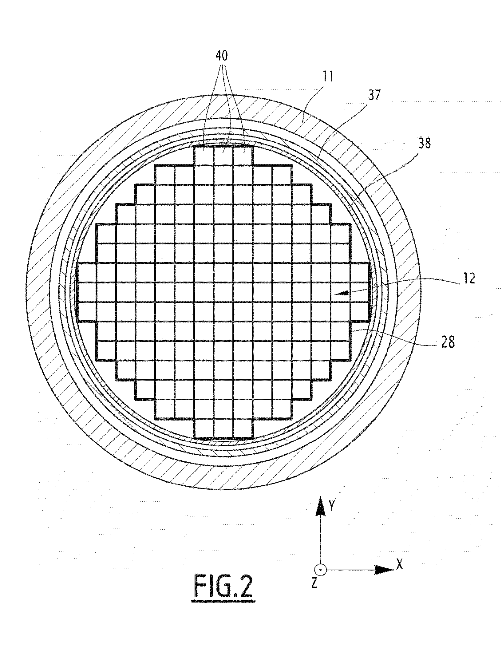
[0059]In FIG. 1, a nuclear reactor 10 comprises, as is known per se, a vessel 11 and a core 12 positioned inside the vessel 11.

[0060]The nuclear reactor 10 also comprises one or more steam generators 14, one or more turbines 16 each coupled to an electricity generator 18, and one or more condensers 20, only one of each of these elements being shown in FIG. 1.

[0061]The nuclear reactor 10 further comprises a primary circuit 22 equipped with pumps 24 and in which a fluid flows, along the path embodied by the arrows in FIG. 1. This fluid in particular rises inside the vessel 11 through the core 12 to be heated therein while ensuring refrigeration and moderation in the core 12. The primary circuit 22 further comprises a pressurizer 26 making it possible to regulate the pressure of the fluid flowing in the primary circuit 22.

[0062]The nuclear reactor 10 is, for example, a pressurized water reactor (PWR), and the fluid flowing in the primary circuit 22 is then pressurized water.

[0063]Alter...


PUM


Abstract

A method for simulating the flow of a fluid in a vessel of a nuclear reactor is provided. The nuclear reactor includes the vessel and a core inside the vessel, the core including nuclear fuel assemblies, each one extending in an axial direction, including nuclear fuel rods and a grid for maintaining the rods, and being spaced apart from another by a clearance between the grids in a transverse direction.This method for simulating a fluid flow in the vessel of a nuclear reactor includes determining of head loss coefficients in the core, and computing the fluid pressure and speed component(s) in the core using the equation: ∇P=−K×V where P is the component of the fluid pressure, K is a matrix including the determined head loss coefficients, and V is a vector including the fluid speed component(s).A transverse head loss coefficient in the assemblies is determined from a transverse Reynolds number, and an axial head loss coefficient in the clearance is from the dimension of the clearance in the transverse direction.

Description

[0001]The present invention relates to a method for simulating the flow of a fluid in a vessel of a nuclear reactor.[0002]The invention also relates to a method for calculating a mechanical deformation of at least one nuclear fuel assembly of a core positioned inside the vessel of the nuclear reactor.[0003]The invention also relates to a computer program product for implementing such a simulation method and a computer program product for implementing such a method for calculating the mechanical deformation.[0004]The invention applies to reactors having a coolant fluid, in particular reactors using a cooling gas or liquid: light water, heavy water, salt or molten metal.[0005]Hereinafter, the invention will be described for an application to light water reactors, for example pressurized water reactors, and the fluid circulating inside the vessel is then pressurized water.BACKGROUND OF THE INVENTION[0006]Traditionally, the nuclear reactor of a pressurized water reactor comprises a vess...

Claims


Application Information

Patent Timeline
IPC IPC(8): G21D3/00G06F17/18
CPCG21D3/001G21D2003/005G06F17/18G21D3/005Y02E30/00Y02E30/30
Inventor GOREAUD, NICOLASCHAZOT, BENJAMINGALPIN, JEREMYSALAUN, HUBERTMERY DE MONTIGNY, ELODIE
Owner AREVA NP SAS
Learn More