Electric cable structural body, electric connection structure, and method for producing electric cable structural body

Active Publication Date: 2016-02-04
FURUKAWA ELECTRIC CO LTD +1
View PDF5 Cites 13 Cited by
  • Summary
  • Abstract
  • Description
  • Claims
  • Application Information

AI Technical Summary

Benefits of technology

The present invention provides a way to connect electrical conductors accurately and efficiently at points where they overlap, making it easier to create a desirable wiring pattern. It also allows for easy and accurate positioning of the electric cables in a group intersection point without the need for a dedicated jig.

Problems solved by technology

Therefore, there is an undesirable possibility that the connection is made at a wrong intersection portion, or that the connection at the intersection portion by use of the crimp terminal is troublesome.
There is another undesirable possibility that the number of components including the crimp terminal is increased, which fails to improve the production efficiency or to reduce the cost sufficiently.

Method used


Image

  • Electric cable structural body, electric connection structure, and method for producing electric cable structural body
  • Electric cable structural body, electric connection structure, and method for producing electric cable structural body
  • Electric cable structural body, electric connection structure, and method for producing electric cable structural body

Examples


example 3

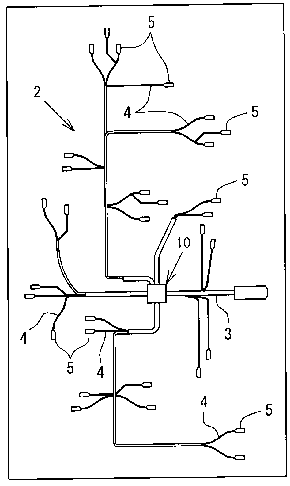
[0201]In a vehicle such an automobile or the like, a wire harness connection structure 100 mutually connecting a power source, a control device such as an ECU (Engine Control Unit) and an electric device such as an audio device, a direction indicator or the like includes, as shown in FIG. 22, a wire harnesses W and a branch connector 110 connecting the wire harness W.

[0202]The wire harness W includes a backbone harness Wm connected with the power source or the control device, and branch harnesses Ws that are each branched from the backbone harness Wm and has, at an end thereof, a connector C connected with each of electric devices. The branch connector 110 is connected with at least one of the backbone harness Wm and the branch harnesses Ws.

[0203]With reference to FIG. 23 through FIG. 27, the branch connector 110 in the harness connection structure 100 will be described in detail.

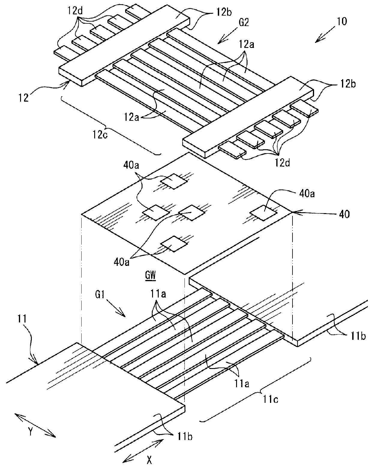
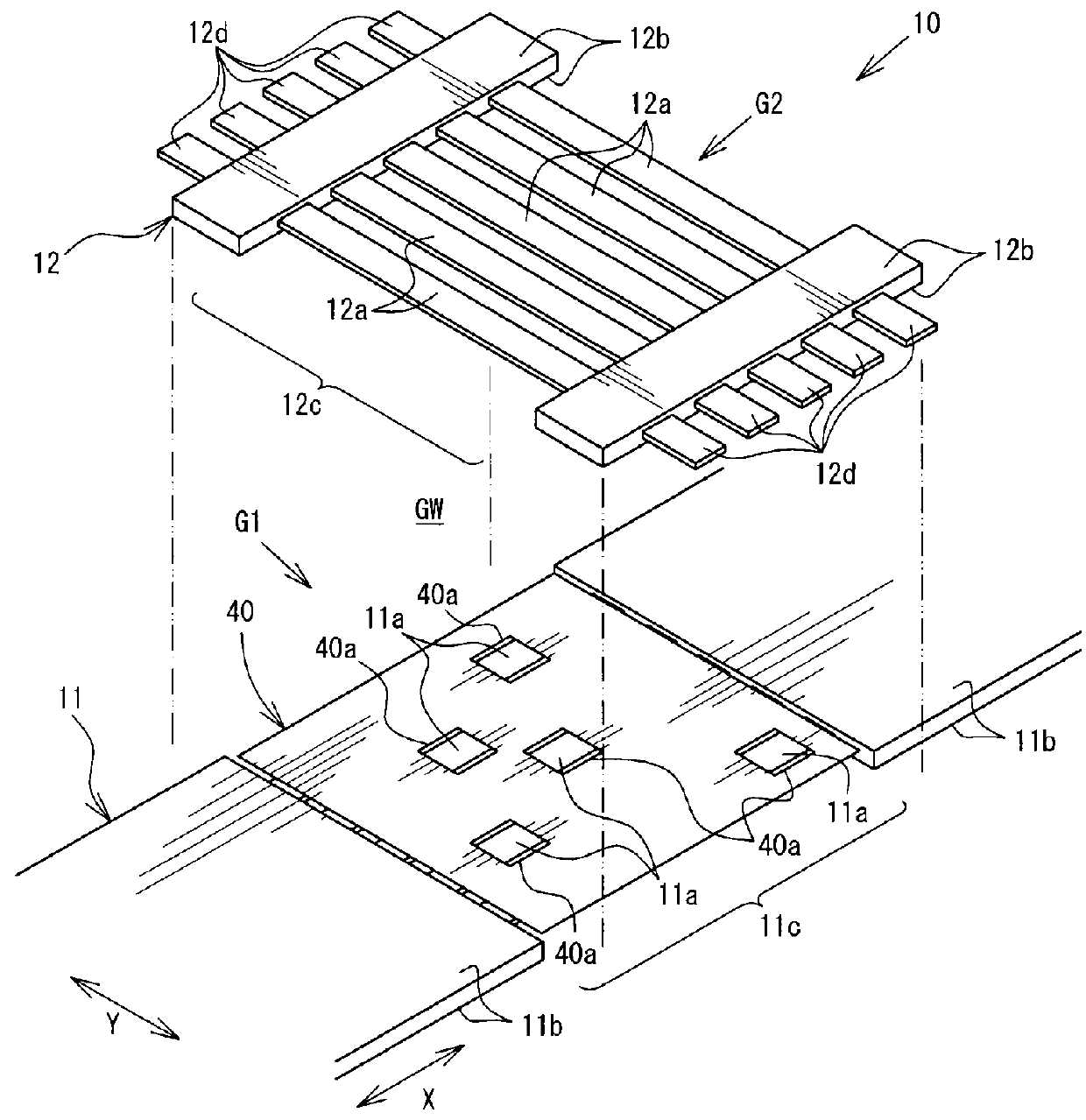
[0204]As shown in FIG. 23 through FIG. 27, the branch connector 110 includes an electric cable group int...

example 1

Production Method Example 1

[0218]First, in an insulating cover removal step, for example, laser light L is directed toward a predetermined portion of the first covered electric cable 131A to remove a predetermined position in the insulating cover 133A. The predetermined portion extends in the longitudinal direction, and the insulating cover 133A in this portion is removed along the entirety of a surface thereof in the circumferential direction. As a result, the core wire 132A is exposed in the conductor exposed portion 132A1. Similarly, the insulating cover 133B is removed from the second covered electric cable 131B to expose the core wire 132B in the conductor exposed portion 132B1.

[0219]In an intersection positional arrangement step, the first covered electric cable 131A and the second covered electric cable 1313 are put to overlap each other such that the conductor exposed portion 132A1 of the first covered electric cable 131A and the conductor exposed portion 132B1 of the second...

example 2

Production Method Example 2

[0266]Now, a method for producing the intersecting electric cable group 130 different from production example 1 will be described in detail with reference to FIGS. 29A and 29B through FIG. 31. In this example also, the first covered electric cable 131A and the second covered electric cable 131B are welded together in the conductor joining step to form the intersecting electric cable group 130.

[0267]The elements identical with those of production method example 1 will bear the same reference signs, and detailed descriptions thereof will be omitted. FIGS. 29A and 29B show the conductor joining step in which the conductor exposed portions 132A1 and 132B1 are jointed together by laser irradiation. FIG. 30 shows the conductor joining step in which the conductor exposed portions 132A1 and 132B1 are jointed together by laser irradiation. FIG. 30 shows the covered electric cables 131 intersecting each other, and one of the covered electric cables 131 is shown with...


PUM


Abstract

A first direction exposed conductor group includes a plurality of exposed conductor portions of a first flat cable, and a second direction exposed conductor group includes a plurality of exposed conductor portions of a second flat cable. The plurality of exposed conductor portions are located parallel to each other, and the plurality of exposed conductor portions are located parallel to each other. The first direction exposed conductor group and the second direction exposed conductor group intersect and overlap each other to form an intersection overlap portion. An intersection insulating film is provided between the first direction exposed conductor group and the second direction exposed conductor group at the intersection overlap portion. The exposed conductor portions and the exposed conductor portions facing each other via windows of the intersection insulating film are connected to be conductive to each other. Thus, an electric cable structural body is provided.

Description

CROSS-REFERENCE TO RELATED APPLICATIONS[0001]This application is a continuation application of PCT International Application No. PCT / JP2014 / 052558 filed Feb. 4, 2014, which claims priority to Japanese Application No 2013-020028 filed Feb. 5, 2013, and Japanese Application No. 2013-043700 filed on Mar. 6, 2013, each of which are herein incorporated by reference in their entity for all purposes.TECHNICAL FIELD[0002]The present invention relates to an electric cable structural body, an electric connection structure, and a method for producing an electric cable structural body.[0003]Alternatively, the present invention relates to an electric cable structural body and an electric connection structure, by which in an electric cable group intersection portion including a plurality of electric cable intersection portions where first covered electric cables and second covered electric cables intersect each other, a covered electric cable and a second covered electric cable are connected to e...

Claims


Application Information

Patent Timeline
IPC IPC(8): H01B7/00H01R13/02H01B7/08H01R43/16
CPCH01R13/02H01B7/0823H01B7/0045H01R43/16H01R4/021H01R12/61H01B7/009B60R16/0207
Inventor TOMINAGA, MICHIHIKOSAKAKI, NAOYANISHIMURA, MAKOTOIKEDA, TAKEHIDETABA, ATSUSHIKOMATSU, TAKUYA
Owner FURUKAWA ELECTRIC CO LTD
Why Eureka
Try Eureka