
Filament for mass spectrometric electron impact ion source

a mass spectrometric and electron impact technology, applied in the direction of ion beam tubes, particle separator tube details, instruments, etc., can solve the problems of ion beam loss in the ion source, and no longer meeting modern requirements in an optimal way

Active Publication Date: 2016-01-28
BRUKER DALTONIK GMBH & CO KG
View PDF3 Cites 10 Cited by
  • Summary
  • Abstract
  • Description
  • Claims
  • Application Information

AI Technical Summary

Benefits of technology

The invention is a system for an EI ion source which includes a filament and multiple current supply posts. These current supply posts divide the filament into segments and supply or return electric current to at least two segments. The filament and segments are made of materials like tungsten or rhenium, and the current supply posts are shaped to heat them with the current to match the filament temperature. To achieve uniform temperature across the filament, some material may be removed from some segments to have the same electron emission. This can be controlled by measuring electron emission. Overall, the system provides a more efficient and uniform heating of the filament for ion source applications.

Problems solved by technology

Ion sources with slits generating non-cylindrical ion beams no longer fulfill modern requirements in an optimum way.
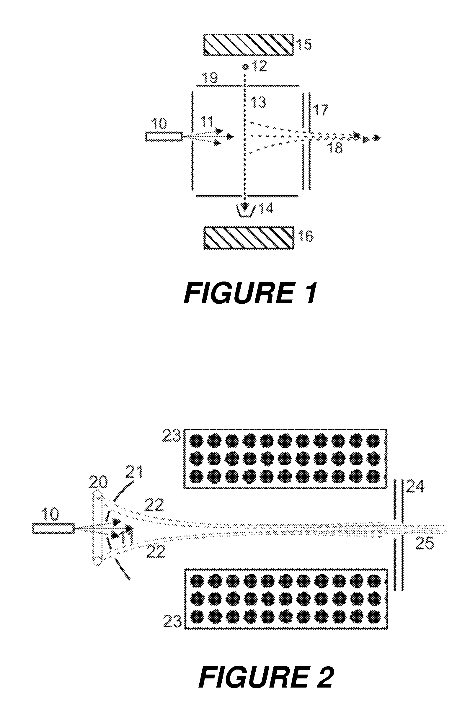
This mismatch may lead to ion beam losses in the ion source or in the ion extraction optics, or to an undesired widening of the ion energy distribution, or to an ion beam symmetry distortion further down the MS.
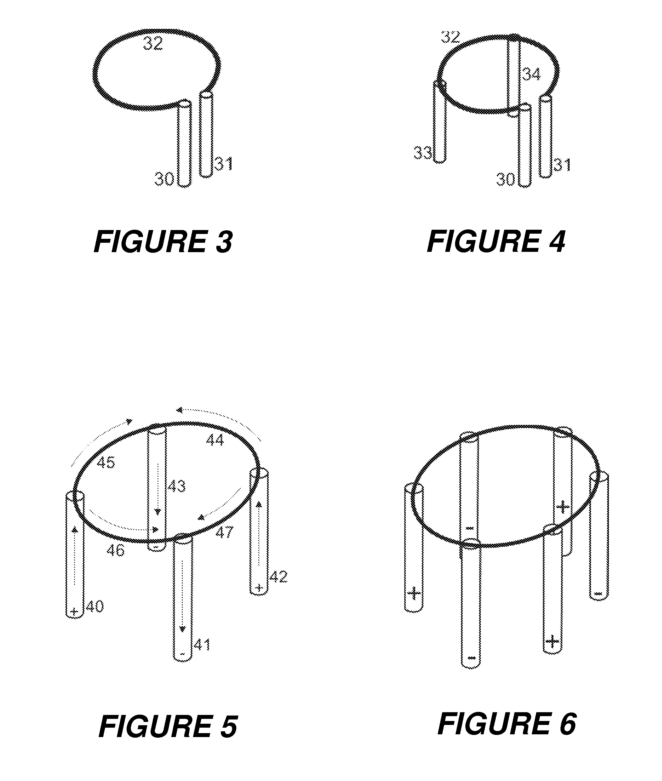
Circular or cylindrically symmetric filament assemblies, such as ring-shaped filaments, however, run the risk of losing shape after cycles of repeated heating and cooling.
Providing additional support posts used to reduce the freedom to deform, as shown in FIG. 4 for example, results in heat being carried away via the posts and leads to different electron emission characteristics over the regions of non-uniform temperature.

Method used


Image

  • Filament for mass spectrometric electron impact ion source
  • Filament for mass spectrometric electron impact ion source
  • Filament for mass spectrometric electron impact ion source

Examples


Embodiment Construction

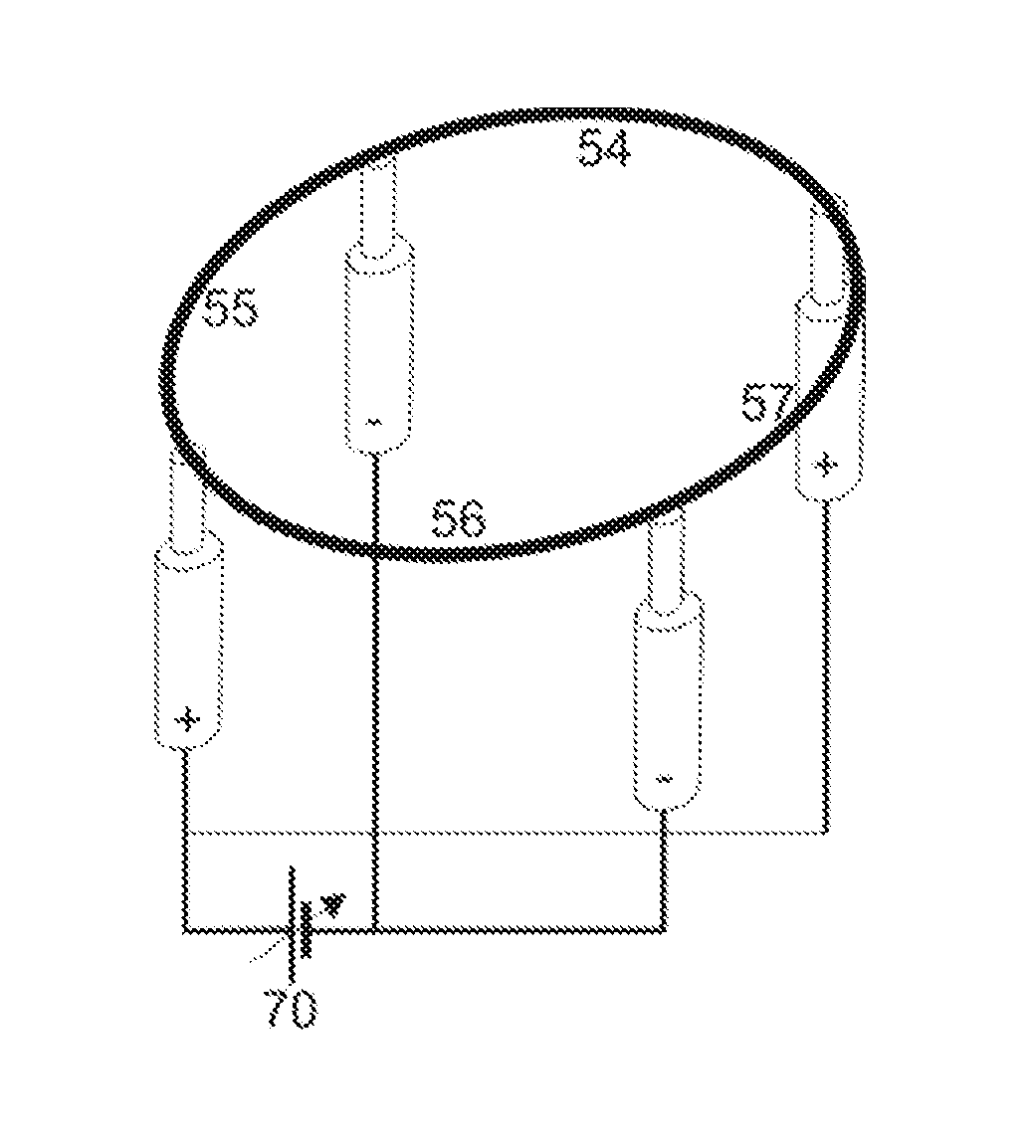
[0028]The invention provides a cathode system for an EI ion source comprising a filament (electrically) divided into segments by current supply posts, each current supply post supplying or returning the current for at least two segments of the filament. Each segment is connected at both ends to supply posts supplying or returning the electric current to heat the filament. The connection may be performed as usual by spot welding, or by laser spot welding. A good electric contact is achieved if the filament is partly embedded into a groove at the top of the current supply post before spot welding. The segments may be arranged in a row, or parallel to each other. Segments arranged in a row may form a closed loop, for instance, a ring. FIG. 5 shows an embodiment of a ring-shaped filament divided into four segments by four current supply posts; in FIG. 6, an example of (electrically) dividing the ring-shaped filament into six segments is depicted. FIG. 8 presents a grid-like bundle of fi...


PUM


Abstract

The invention provides a cathode system for an Electron Ionization (EI) source comprising a filament and current supply posts, the current supply posts dividing the filament into segments and each current supply post supplying or returning the current for at least two segments of the filament. Each filament segment is connected, for instance by spot welding, to the supply posts delivering the heating current. The filament segments may be arranged in a row, or substantially parallel to each other. Filament segments arranged in a row may form a closed loop, for instance, a ring. Other embodiments encompass the filament shape of a helical coil.

Description

BACKGROUND OF THE INVENTION[0001]1. Field of the Invention[0002]The invention relates to filaments used as electron emitting cathodes in electron impact ion sources for mass spectrometers (MS).[0003]2. Description of the Related Art[0004]Electron impact ionization, or more correctly Electron Ionization (EI), is a common type of ionization in gas chromatography-mass spectrometry (GC-MS). The EI source offers predictable fragmentation favorable for compound identification using commercially available libraries with several hundred thousand reference spectra, e.g., the library of the National Institute for Standards and Technology (NIST). The EI source furthermore offers uniform response for most compounds because the ionization efficiency is mostly not compound dependent.[0005]The classical EI ion source is the cross-beam ion source wherein an electron beam generated by a linear glow cathode is accelerated through a slit to about 70 electronvolts, is guided by a weak magnetic field th...

Claims


Application Information

Patent Timeline
IPC IPC(8): H01J49/14
CPCH01J49/147H01J27/205H01J49/08
Inventor SPLENDORE, MAURIZIOMUNTEAN, FELICIANMOELLER, ROY P.
Owner BRUKER DALTONIK GMBH & CO KG
Learn More