Transparent display

a display and transparent technology, applied in the field of transparent displays, can solve the problems of distorted view of the image behind the display, window mode does not provide a proper view of the scene behind the window, and the display is not yet available with 3d viewing capability, so as to improve the contrast ratio of the display and reduce the effect of glar

Inactive Publication Date: 2016-01-28
KONINKLJIJKE PHILIPS NV
View PDF3 Cites 7 Cited by
  • Summary
  • Abstract
  • Description
  • Claims
  • Application Information

AI Technical Summary

Benefits of technology

[0008]This arrangement provides a polarizer between the pixels, in the area which provides the transparency of the display. In the ...

Problems solved by technology

Transparent displays are not yet available with 3D viewing capability, and in particular not yet using glasses-free autostereoscopic approaches, such as with lenticular lenses.
A conventional combination of a lenticular lens on top of a display, as is common in autostereoscopic 3D displays, causes a problem if the display is transparent ...

Method used


Image

  • Transparent display
  • Transparent display
  • Transparent display

Examples


first embodiment

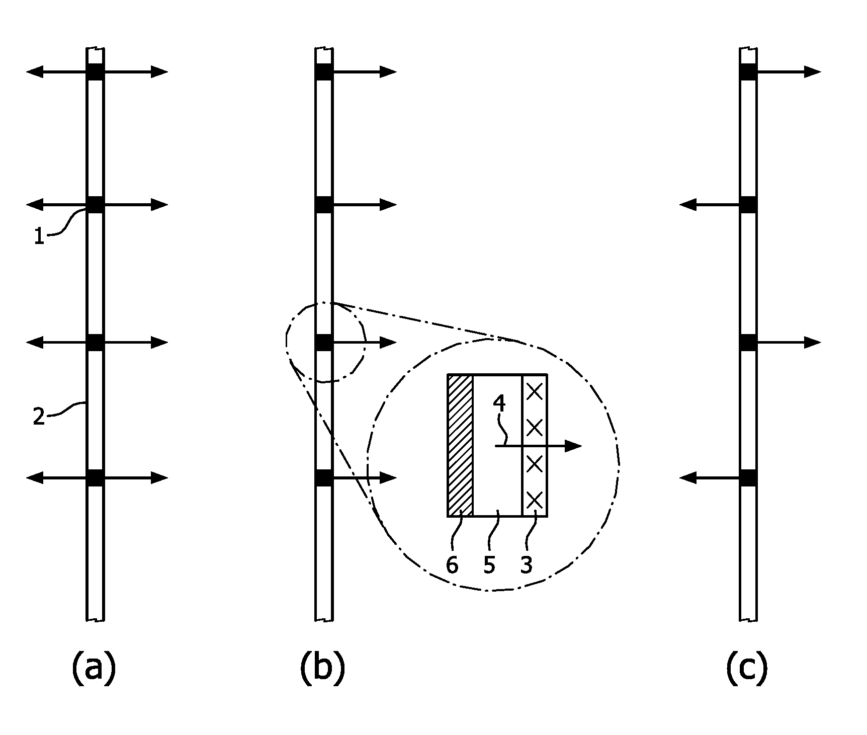
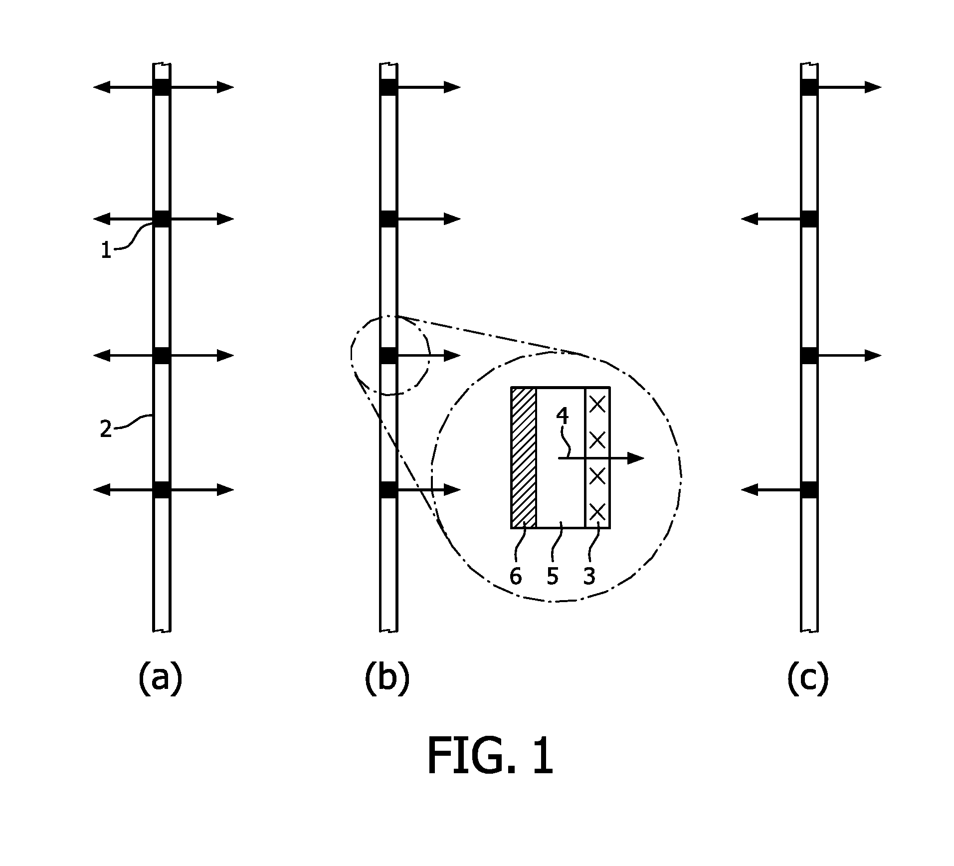
[0045]A first embodiment provides a single sided 2D transparent emissive display with in-plane polariser, and is based on the panel shown in FIG. 1(b).

[0046]The role of the polariser is to improve the contrast ratio of the display for a viewer on the right hand side of the display in the case that the light incident on the left hand side of the display to be transmitted by the display is polarised. This is the configuration shown in FIG. 1(b). A well-known cause of such polarisation is reflection of light by water, snow, ice or other reflective surfaces.

[0047]With a suitable choice of polariser, such as with crossed polarisation if the light is linearly polarised, it is possible to greatly reduce glare for example from reflected sunlight whilst still allowing a considerable transparency of the display.

[0048]As the reflection from a water surface for example has primarily polarised light parallel to the plane of the surface, then the display should preferably have a vertical polarise...

example 1

[0067]

state A=linearly horizontally polarized

state B=linearly vertically polarized

example 2

[0068]

state A=clockwise circularly polarized

state B=counter-clockwise circularly polarized

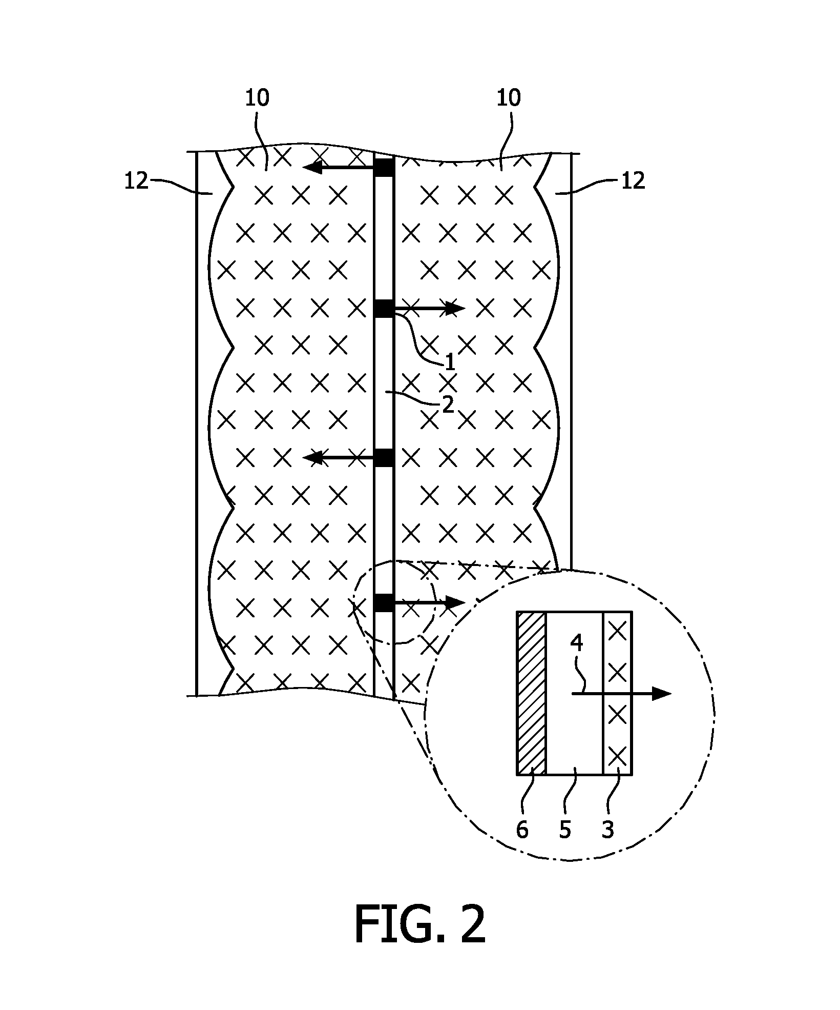
[0069]In FIG. 2, dashed crosses and dashed lines are used to indicate orthogonal polarization states for the various optical components. For the polarization transmitted through polarizer 3, the material of the lens has a different refractive index to the replica 12 and therefore acts as a lens for this polarization.

[0070]The dashed crosses indicate that the optical element works on polarization state A, which means:

[0071]For a polariser, it transmits state A and absorbs / reflects state B;

[0072]For a lens, state A effectively sees the birefringent lens and replica 10,12 as a lenticular lens, whereas state B effectively sees the birefringent lens and replica as a spacer.

[0073]The dashed lines indicate that the optical element works on polarization state B, which means:

[0074]For a polariser, it transmits state B and absorbs / reflects state A;

[0075]For a lens, state B effectively sees the birefringe...


PUM


Abstract

A display has an array of light emitting display pixels occupying pixel areas, and a polarizing light transmissive area between the pixel areas. This polarization can be used to improve the contrast ratio of a transparent 2D display. However, it can also be used to enable a transparent 3D display to be formed without distortion of the see-through transparent display function. For this purpose, the light emitting display pixels can emit polarized light orthogonal to the polarization provided by the light transmissive area.

Description

FIELD OF THE INVENTION[0001]This invention relates to transparent displays, and in a preferred set of examples to transparent autostereoscopic displays.BACKGROUND OF THE INVENTION[0002]Transparent displays enable a background behind the display to be viewed as well as the display output. The display thus has a certain level of transmittance. Transparent displays have many possible applications such as windows for buildings or automobiles and show windows for shopping malls. In addition to these large device applications, small devices such as hand held tablets may also benefit from transparent displays, for example to enable a user to view a map as well the scenery ahead though the screen.[0003]It is expected that much of the existing display market will be replaced by transparent displays, for example in the fields of construction, advertisement and public information. Transparent displays are not yet available with 3D viewing capability, and in particular not yet using glasses-fre...

Claims


Application Information

Patent Timeline
IPC IPC(8): G02B5/30G02B30/25G02B30/27G02B30/30H01L27/32H01L51/52H04N13/04
CPCG02B27/26G02B27/2214H04N13/0452H04N13/0456H04N13/0404H01L2251/5323G02B5/3058H01L27/3234H01L27/326H01L51/5281H01L51/5275G02B5/3083H04N13/305H04N13/356H04N13/361G02B30/27G02B30/30H10K59/121H10K50/858H10K50/86H10K2102/3031G02B30/25H10K59/65
Inventor JOHNSON, MARK THOMASKROON, BARTVAN PUTTEN, ELBERT GERJANVDOVIN, OLEXANDR VALENTYNOVYCH
Owner KONINKLJIJKE PHILIPS NV
Why Eureka
Try Eureka