
Separator

a technology of separator and separator plate, which is applied in the field of separator plate, can solve the problems of high manufacturing cost, large separator with an increased size and volume, and heavy weight, and achieve the effect of improving separation efficiency without increasing the size and weight of the separator pla

Active Publication Date: 2016-01-28
HANWHA POWER SYST CO LTD
View PDF45 Cites 0 Cited by
  • Summary
  • Abstract
  • Description
  • Claims
  • Application Information

AI Technical Summary

Benefits of technology

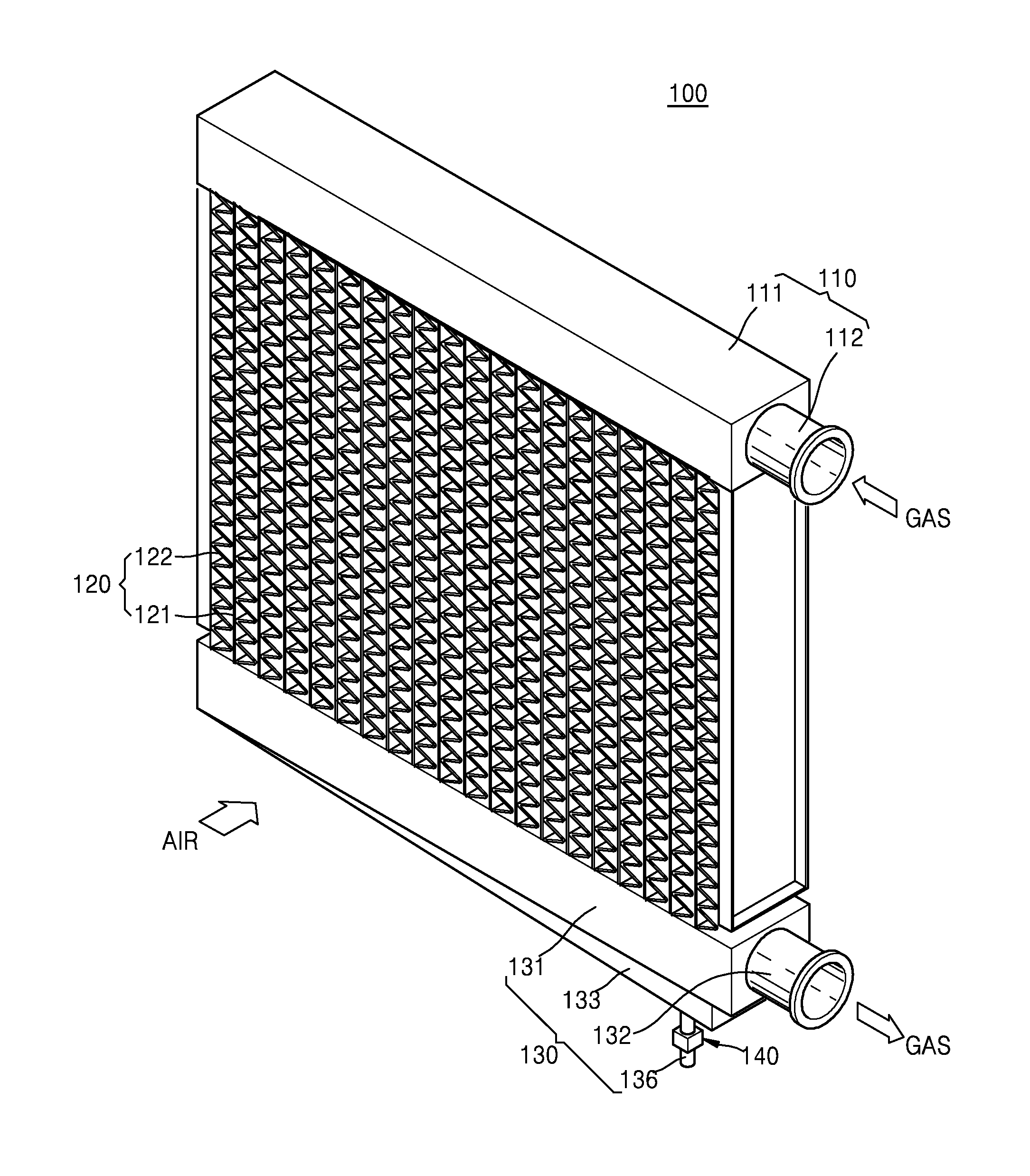
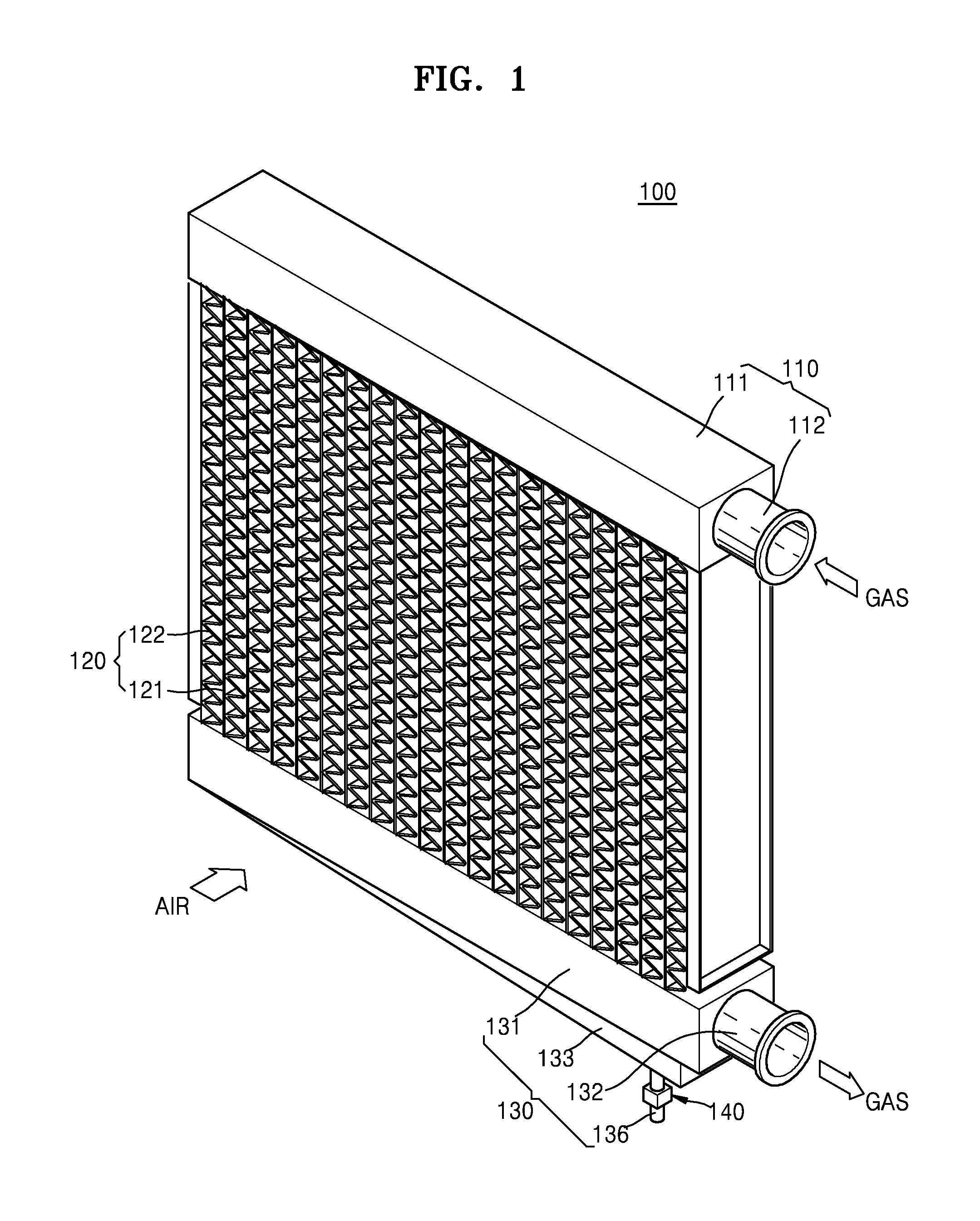
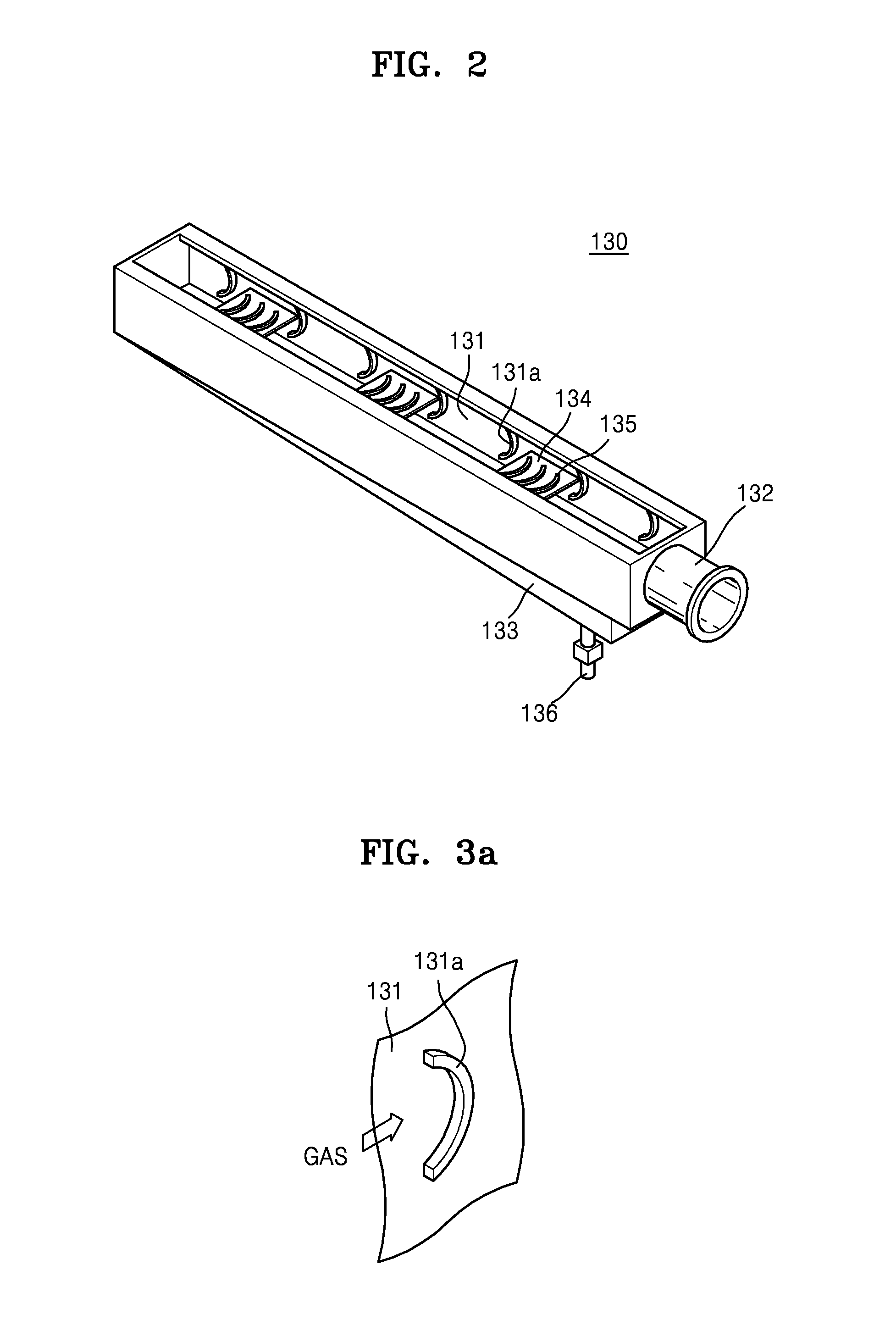
The patent describes a separator that improves separation efficiency without increasing its size and weight. The separator includes a first header, a core, and a second header. The gas flows through the core and gets cooled while passing through at least one flow path. A baffle is provided on the inner wall of the second header to remove moisture from the gas. Another baffle may also be added to reduce the speed at which the gas moves. Overall, this design allows for more efficient separation of gas.

Problems solved by technology

Also, a large separator with an increased size and volume may be heavy and require a high manufacturing cost.

Method used


Image

  • Separator
  • Separator
  • Separator

Examples


Embodiment Construction

[0032]The inventive concept will now be described more fully with reference to the accompanying drawings, in which exemplary embodiments of the inventive concept are shown. The inventive concept may, however, be embodied in many different forms and should not be construed as being limited to the exemplary embodiments set forth herein; rather, the exemplary embodiments are provided so that this disclosure will be thorough and complete, and will fully convey the concept of the inventive concept to those skilled in the art. The terms used in the present specification are merely used to describe particular embodiments, and are not intended to limit the inventive concept. An expression used in the singular encompasses the expression of the plural, unless it has a clearly different meaning in the context. In the present specification, it is to be understood that the terms such as “including,”“having,” and “comprising” are intended to indicate the existence of the features, numbers, steps,...


PUM

PropertyMeasurementUnit
areaaaaaaaaaaa
moving speedaaaaaaaaaa
distanceaaaaaaaaaa

Abstract

Provided is a separator including: a first header into which gas flows from an exterior of the separator; a core connected to the first header and including at least one flow path configured to cool the gas flowing from the first header through the flow path; and a second header connected to the core and configured to guide the gas passing through the at least one flow path to the exterior of the separator, wherein the second header includes at least one first baffle provided on an inner wall of the second header and configured to remove moisture from the gas.

Description

CROSS-REFERENCE TO RELATED APPLICATION[0001]This application claims priority from Korean Patent Application No. 10-2014-0095001, filed on Jul. 25, 2014, in the Korean Intellectual Property Office, the disclosure of which is incorporated herein by reference in its entirety.BACKGROUND[0002]1. Field[0003]Apparatuses consistent with exemplary embodiments relate to an apparatus, and more particularly, to a separator.[0004]2. Description of the Related Art[0005]The durability and operational efficiency of an apparatus using gas as a fuel, such as a multistage compressor, a turbine, or a gas turbine, may be improved by efficiently removing moisture from the gas. The moisture included in the gas may be removed by providing a separator in an area where the gas flows into the apparatus. Also, the separator may be used to condense and extract the moisture from the flowing gas and supply dry gas to the apparatus described above. The gas passing through the separator may have a differential pres...

Claims


Application Information

Patent Timeline
Patent Type & Authority Applications(United States)
IPC IPC(8): B01D5/00
CPCB01D5/009B01D5/0003B01D53/265
Inventor PARK, HOYOULPARK, HONGGI
Owner HANWHA POWER SYST CO LTD
Learn More