
Ophthalmic surgical microscope with adaptive optics for optical wavefront compensation

a technology of optical wavefront compensation and surgical microscope, which is applied in the field of ophthalmic surgical microscope, can solve the problems of static vision problems of the doctor and/or the patient, affecting the efficacy of the surgical procedure, and dynamic errors that can arise during the surgical procedure, so as to remove optical aberrations

Active Publication Date: 2016-01-28
ALCON INC
View PDF2 Cites 1 Cited by
  • Summary
  • Abstract
  • Description
  • Claims
  • Application Information

AI Technical Summary

Benefits of technology

The patent describes a solution to improve the vision of a doctor and patient during eye surgery by using special optical elements and sensors to remove any distortions or errors in the optical path. This results in a better ability to see fine details and perform the surgical procedure with greater precision.

Problems solved by technology

This can be challenging, however, because of artifacts of the doctor's eye and / or the patient's eye.
For example, the doctor and / or the patient can have static vision problems.
Further, dynamic errors can arise during a surgical procedure.
The artifacts of the doctor's eye and / or the patient's eye interfere with the doctor's vision of the surgical field and can hinder the efficacy of a surgical procedure.
Wearing spectacles during the surgical procedure, however, can be uncomfortable for a doctor.
However, no microscope currently compensates for high order aberrations of the doctor's eye.
And no microscope currently compensates for astigmatism and high order aberrations of the patient's eye.
Further, no microscope compensates for dynamic errors that arise during the surgical procedure.

Method used


Image

  • Ophthalmic surgical microscope with adaptive optics for optical wavefront compensation
  • Ophthalmic surgical microscope with adaptive optics for optical wavefront compensation
  • Ophthalmic surgical microscope with adaptive optics for optical wavefront compensation

Examples


Embodiment Construction

[0014]In the following description specific details are set forth describing certain embodiments. It will be apparent, however, to one skilled in the art that the disclosed embodiments may be practiced without some or all of these specific details. The specific embodiments presented are meant to be illustrative, but not limiting. One skilled in the art may realize other material that, although not specifically described herein, is within the scope and spirit of this disclosure.

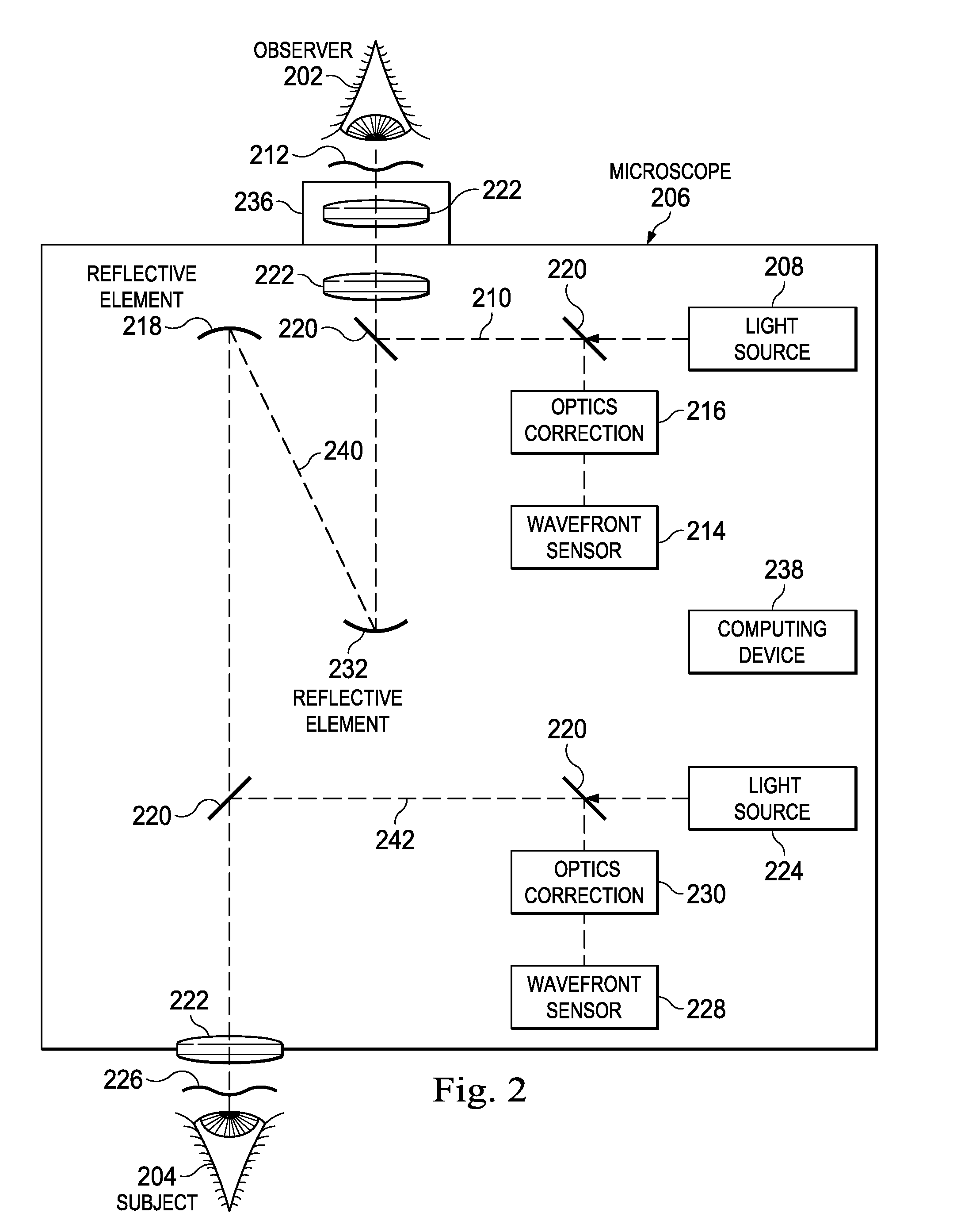
[0015]The present disclosure describes an ophthalmic surgical microscope with adaptive optical element(s) and wavefront sensor(s). The adaptive optical element and the wavefront sensor can be implemented in optical paths associated with the doctor and / or the patient. For example, a laser can be projected on the doctor's retina. A wavefront of light reflected from the retina can be detected by the wavefront sensor. The wavefront sensor can determine if the wavefront is curved (e.g., it includes phase aberration...


PUM


Abstract

An ophthalmic surgical microscope can include a first light source configured to project a first light beam at an observer's eye. The microscope can include a first wavefront sensor. The first wavefront sensor can be configured to determine aberrations in the first reflection wavefront of a reflection of the first light beam. The microscope can include adaptive optical element(s). The adaptive optical element(s) can be controlled to modify the phase of incident light. The microscope can include a computing device in communication with the first wavefront sensor and the adaptive optical element(s). The computing device can be configured to generate the control signal to compensate for the aberrations and to provide the control signal to the adaptive optical element(s). A second light source and second wavefront sensor can be provided to compensate for aberrations of a subject's eye.

Description

BACKGROUND[0001]1. Technical Field[0002]Embodiments disclosed herein are related to ophthalmic surgical microscopes. More specifically, embodiments described herein relate to an ophthalmic surgical microscope including adaptive optical element(s) and wavefront sensor(s) to dynamically compensate for optical aberrations.[0003]2. Related Art[0004]Doctors can use surgical microscopes during ophthalmic surgical procedures to see fine details of a patient's eye. A successful procedure can depend on the doctor's ability to view the patient's eye clearly using the microscope. This can be challenging, however, because of artifacts of the doctor's eye and / or the patient's eye. For example, the doctor and / or the patient can have static vision problems. These can include refractive errors, astigmatism, other low order aberrations, and / or high order aberrations. Further, dynamic errors can arise during a surgical procedure. These include the presence of tear film in the doctor's eye, saline sol...

Claims


Application Information

Patent Timeline
Patent Type & Authority Applications(United States)
IPC IPC(8): A61B3/13A61B3/00A61B3/10G02B26/08G02B27/00
CPCA61B3/13A61B3/1015G02B27/0068G02B26/0825A61B3/0025A61B3/12A61F9/007A61F2009/00848G02B21/0012G02B21/365
Inventor ARTSYUKHOVICH, ALEXANDER, N.
Owner ALCON INC
Learn More