
Fixing device

a fixing belt and fixing plate technology, applied in the direction of instruments, electrographic process devices, optics, etc., can solve the problems of difficult to meet the recording material, excessive temperature increase, and limitation of the number of species of the heating region of the fixing bel

Inactive Publication Date: 2016-01-21
CANON KK
View PDF7 Cites 7 Cited by
  • Summary
  • Abstract
  • Description
  • Claims
  • Application Information

AI Technical Summary

Benefits of technology

The present invention provides a fixing device for a recording material. The device includes a rotatable heating member and a rotatable pressing member that fix a toner image on the recording material. The heating mechanism selectively heats regions of the heating member based on the size of the recording material. The pressing member includes a base layer and an elastic layer with a needle-like filler that has high thermal conductivity in the longitudinal direction of the press. The elastic layer has thermal conductivity that is 6 times to 900 times higher in the longitudinal direction than in the thickness direction. This design ensures efficient heating of the recording material and provides better quality printing.

Problems solved by technology

In such a fixing device, in the case where a small-sized recording material is continuously subjected to fixing of a toner image thereon, there is a liability that a region where the fixing belt does not contact the recording material (hereinafter referred to as a non-passing region) excessively increases in temperature.
However, there are various sizes of recording materials usable in the market, but there is a limitation on the number of species of the heating region of the fixing belt.
That is, although the fixing device can meet the recording material (e.g., a regular-sized paper) having a size assumed to be frequently used, but it is difficult to meet the recording material (e.g., an irregular-sized paper) having a size which is not assumed to be frequently used by the user.
In this case, there is a liability that the excessive temperature rise in the non-pressing region generates.

Method used

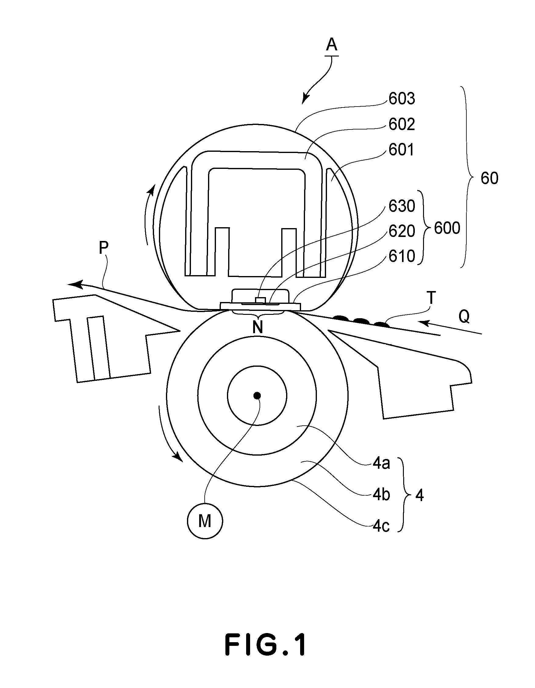

Image

  • Fixing device
  • Fixing device
  • Fixing device

Examples


embodiment

(1) Image Forming Portion

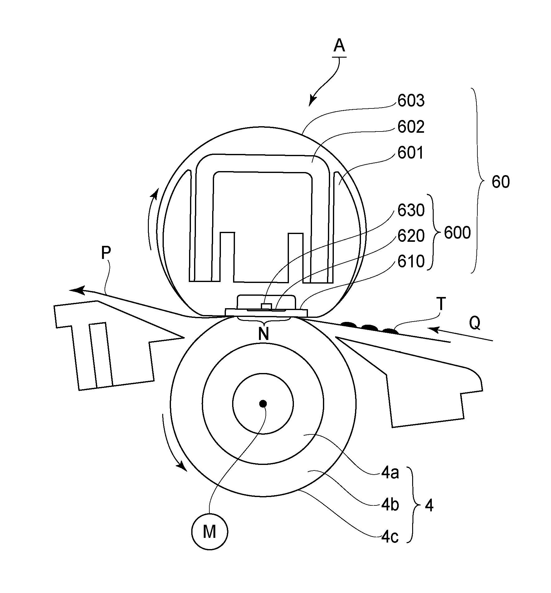
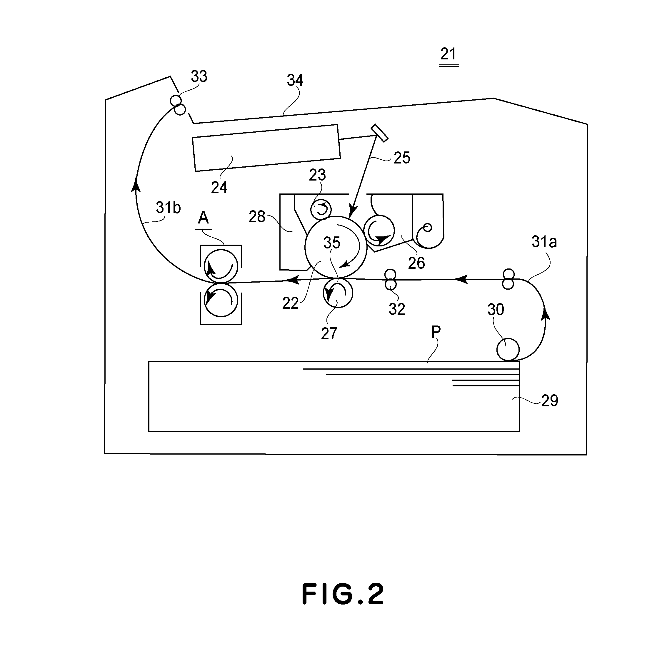
[0026]FIG. 2 is a schematic sectional view showing a structure of an example of an image forming apparatus 21 in which an image heating apparatus in accordance with the present invention as a fixing device A.

[0027]This image forming apparatus 21 is a laser printer of an electrophotographic type and includes a photosensitive drum 22 as an image bearing member for bearing a latent image. The photosensitive drum 22 is rotationally driven in the clockwise direction of an arrow at a predetermined speed, and another surface thereof is electrically charged uniformly to a predetermined polarity and a predetermined potential by a charging device 23. The uniformly charged surface of the photosensitive drum 22 is subjected to laser scanning exposure to light 25 of image information by a laser scanner (optical device) 24. As a result, on the surface of the photosensitive drum 22, an electrostatic latent image of the image information obtained by the scanning exposure is...


PUM


Abstract

A fixing device includes a rotatable heating member and a rotatable pressing member which are configured to fix a toner image on a recording material in a nip therebetween; and a heating mechanism configured to selectively heat regions of the rotatable heating member depending on sizes of the recording material when the sizes are predetermined ones of all sizes usable in the fixing device. The rotatable pressing member includes a base layer and a porous elastic layer provided on the base layer and containing a needle-like filler. The elastic layer having a thermal conductivity, with respect to a longitudinal direction thereof, which is 6 times to 900 times a thermal conductivity with respect to a thickness direction thereof.

Description

FIELD OF THE INVENTION AND RELATED ART[0001]The present invention relates to a fixing device. This fixing device is usable in an image forming apparatus such as a copying machine, a printer, a facsimile machine and a multi-function machine having a plurality of functions of these machines.[0002]A fixing device mounted in an image forming apparatus of an electrophotographic type includes a rotatable fixing member. Such as a fixing belt, and includes a rotatable pressing member such as a pressing roller.[0003]In such a fixing device, in the case where a small-sized recording material is continuously subjected to fixing of a toner image thereon, there is a liability that a region where the fixing belt does not contact the recording material (hereinafter referred to as a non-passing region) excessively increases in temperature. Therefore, a constitution in which a region where the fixing belt is heated is limited depending on a size of the recording material to suppress excessive temper...

Claims


Application Information

Patent Timeline
Patent Type & Authority Applications(United States)
IPC IPC(8): G03G15/20
CPCG03G15/206G03G15/2042G03G2215/2035
Inventor TAKADA, SHIGEAKINAKAYAMA, TOSHINORITAMAKI, MASAYUKIAKIYAMA, NAOKIASAKA, AKESHIKAKUBARI, KOICHIARAI, YUTAKAMIURA, JUN
Owner CANON KK
Learn More