
Determining integrity of braking control system

a technology of integrity and braking control, applied in the direction of failsafe aspects, instruments, navigation instruments, etc., can solve the problem that the integrity check of u.s. pat. no. 4,834,465 cannot be used to reliably check the integrity of an accumulator

Active Publication Date: 2016-01-21
AIRBUS OPERATIONS LTD
View PDF3 Cites 5 Cited by
  • Summary
  • Abstract
  • Description
  • Claims
  • Application Information

AI Technical Summary

Benefits of technology

This patent describes a way to supply energy to a brake system on an aircraft or other vehicle. The system uses two energy sources: one is a primary source, like a battery or hydraulic pump, and the other is a secondary source, like a reserve battery or hydraulic tank. The method ensures that the primary source is always used to avoid any failures. However, there are situations where the secondary source may be necessary, like when the primary source is unavailable. The patent suggests two alternatives: either supplying both voltage and hydraulic pressure to the brake system at the same time using the primary source or isolating the secondary source from the brake system and using it only in case of a failure. The technical effect of this patent is to provide a reliable and fail-safe way to supply energy to a brake system in such situations.

Problems solved by technology

Such a low pressure value may be caused by a loss of integrity of the accumulator, but it may also be caused by a healthy accumulator having been full discharged.
Thus the absolute pressure check of U.S. Pat. No. 4,834,465 cannot be used to reliably check the integrity of an accumulator.

Method used


Image

  • Determining integrity of braking control system
  • Determining integrity of braking control system
  • Determining integrity of braking control system

Examples


Embodiment Construction

)

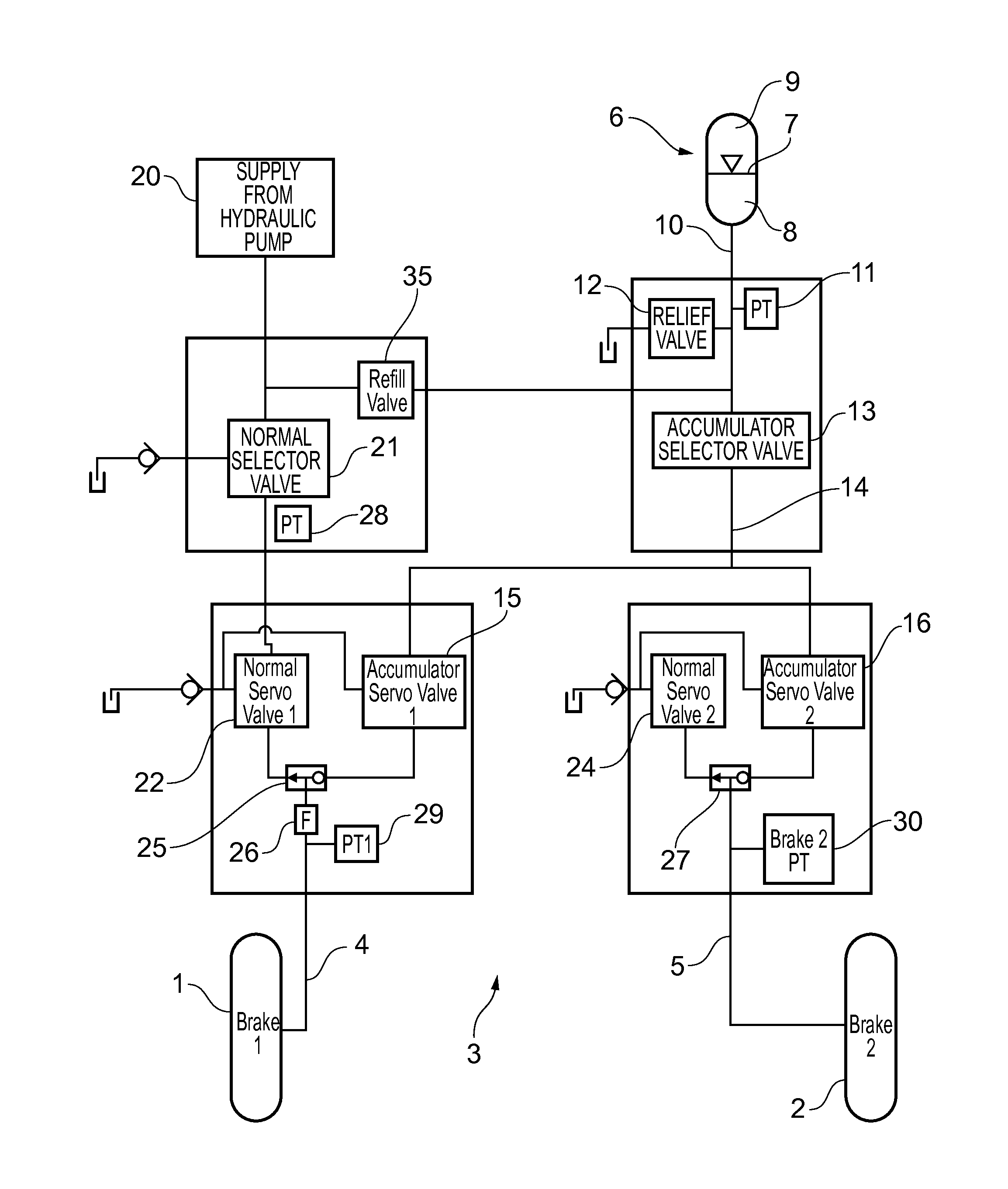
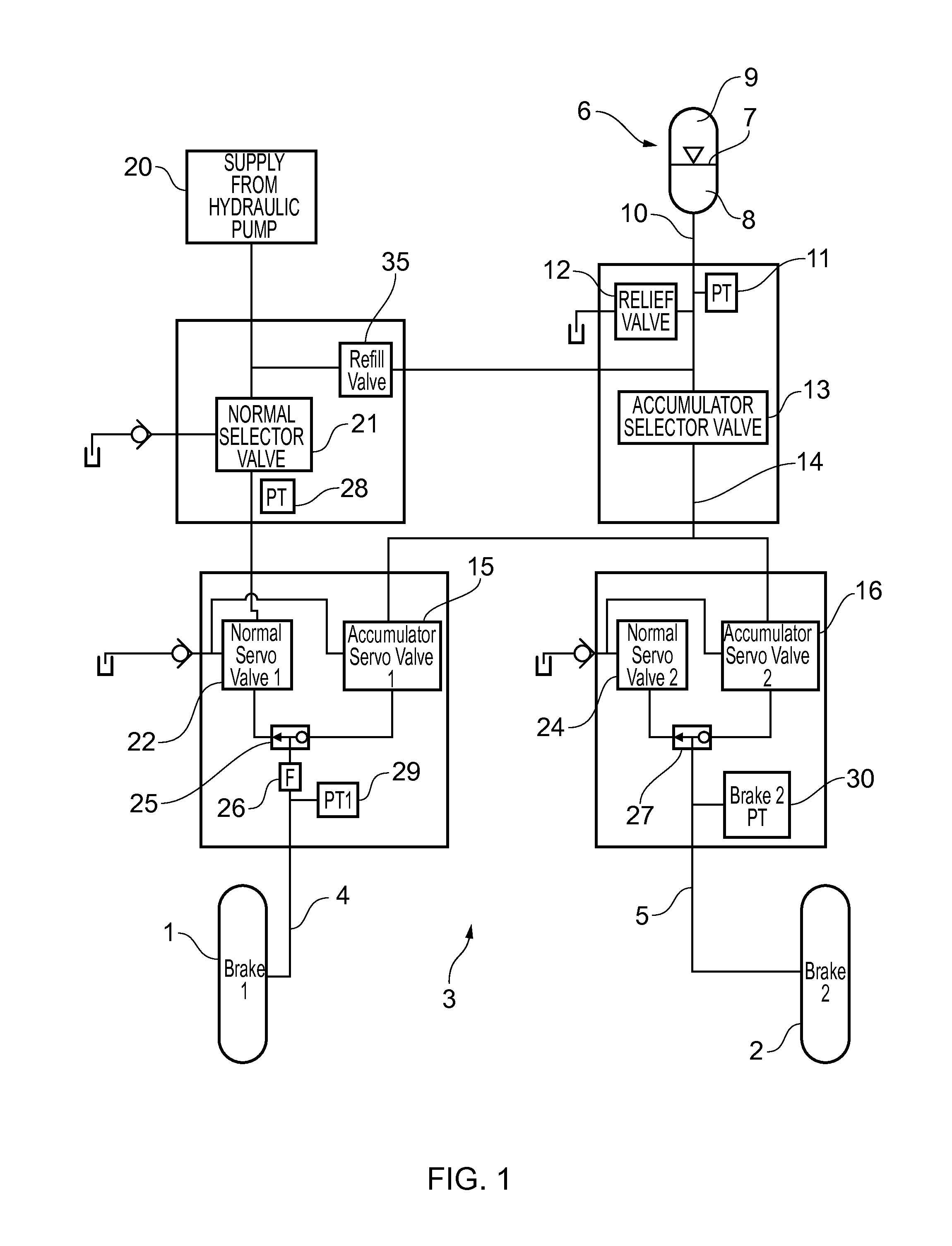
[0034]FIG. 1 shows an aircraft braking system comprising a pair of brakes 1, 2; and a braking control system 3 for applying hydraulic pressure to the brakes on brake lines 4, 5.

[0035]The hydraulic accumulator 6 comprises a piston 7 (although the piston 7 could be replaced by a bladder, diaphragm or other fluid separating device) with hydraulic liquid 8 on one side and compressed gas 9 on the other side. The accumulator has an output line 10 with a pressure sensor 11. If the pressure on the output line 10 exceeds a threshold, then a relief valve 12 opens so excess liquid is fed into a reservoir. Further pressure sensors 28-30 are also provided for sensing the pressure at various other parts of the hydraulic system.

[0036]The output line 10 leads to an accumulator selector valve 13. When the valve 13 is open the accumulator output line 10 is in fluid communication with a line 14 which splits and leads to a pair of accumulator servo valves 15, 16.

[0037]During normal operation, hydrauli...


PUM


Abstract

A method of determining the integrity of an electric or hydraulic energy source of a braking control system. The energy source is charged or discharged, and two or more measurements of voltage or hydraulic pressure are taken from the braking control system. A difference between at least two of the measurements is determined in order to determine a change or rate of change in voltage or hydraulic pressure caused by the charging or discharging of the energy source. The integrity of the energy source is determined by checking whether the change or rate of change in voltage or hydraulic pressure meets predetermined criteria. The check may comprise comparing the change or rate of change of the voltage or hydraulic pressure to a threshold—for instance checking whether the change exceeds a threshold, or falls between an upper threshold and a lower threshold.

Description

FIELD OF THE INVENTION[0001]The present invention relates to a method of determining the integrity of a braking control system including an electric or hydraulic energy source. Preferably, but not exclusively, the braking control system is an aircraft braking control system.BACKGROUND OF THE INVENTION[0002]A hydraulic braking control system of an aircraft is described in U.S. Pat. No. 4,834,465A. The system includes an emergency circuit including a hydraulic accumulator. A pressure sensor of the emergency circuit triggers an alarm when the pressure in the emergency circuit is too low.SUMMARY OF THE INVENTION[0003]A first aspect of the invention provides a method of determining the integrity of a braking control system, the braking control system comprising an electric or hydraulic energy source, the method comprising: charging or discharging the energy source; taking two or more measurements of voltage or hydraulic pressure from the braking control system; analysing at least two of ...

Claims


Application Information

Patent Timeline
Patent Type & Authority Applications(United States)
IPC IPC(8): B60T17/22
CPCB60T17/221B60T17/22B60T17/18B64C25/42B60T2270/40B60T8/325B60T13/662B60T8/1703B60T17/222
Inventor HOWELL, GEORGENAVE, MATTHIEU DELLA
Owner AIRBUS OPERATIONS LTD
Learn More