
Implantable stent

a technology of implantable stents and stents, which is applied in the field of implantable medical devices, can solve the problems of difficult removal of stents, product encrustation is generally susceptible to higher levels of encrustation than metal stents, and is rarely suitable for the intended use in animals. , to achieve the effect of preventing deformation, and reducing the risk of stent damag

Inactive Publication Date: 2016-01-21
MCDONOUGH ARDLE TOMAS
View PDF11 Cites 10 Cited by
  • Summary
  • Abstract
  • Description
  • Claims
  • Application Information

AI Technical Summary

Benefits of technology

The invention is a unique stent design that allows for smaller, better functioning stents to be created. The stent can be produced in different sizes to fit all ureters, minimizing trauma to the patient. The stent is placed using a sheath and an inserter, which can push the stent through the sheath and into the ureter. The stent is made from coiled, solid wires and is coated with a metallic substance for strength and to prevent bacteria adhering to the surface. The stent has a pigtail or loop at the end to prevent migration. Overall, this design allows for improved stent placement in ureters.

Problems solved by technology

These products are generally susceptible to higher levels of encrustation than metal stents because of a reaction between the plastic stent and bacteria in the urinary system.
The encrustation can make the stents difficult to remove, which is obviously problematic.
For this reason, the recommended indwell duration for human use of these plastic stents is only eight weeks, which is rarely suitable for the intended use in animals.
This is particularly problematic when there is a tight stricture, a stone that cannot be easily removed and where the ureter of the patient is between 0.3 mm and 1.0 mm in diameter.
A further issue is an inability to produce smaller diameter stents with current stent designs and stent kits.
Inserting stents that exceed the size of the vessel can cause unnecessary and irreversible dilation of the vessel.
This is an issue where vessels are smaller than any stent available, such as in the ureters or pancreatic ducts of smaller animals, such as cats or small dogs.
The result of placing stents that exceed the size of the vessel is that the stent can never be removed, since the vessel would collapse.
Furthermore, since the size of current stents is larger than the vessel for which they are intended, there is difficulty in placing the current stents.
It would not be possible to use any stent or stent kit previously invented to solve the problems described above.
With regard to metal ureteral stents, the stents and stent kits listed in the prior art quoted in this patent claim would not work for smaller stents.
The coils in patent claim U.S. Pat. No. 4,813,925 are coiled helically, but are not touching, which reduces radial strength.
The wire is a single wire only, which also reduces radial strength and which reduces holding strength in the looped ends of the stent.
There is therefore a higher chance of deformation and inability to maintain its place in a stent such as this in smaller versions of stent use, where wires are akin to thread used in common sewing.
The use of hollow wire to allow for a guidewire to be inserted into the wire to place the stent would also not be possible in smaller wire dimensions.
The stent kit in patent number U.S. Pat. No. 7,550,012 uses a hollow wire, which would not be feasible for smaller stents as wire dimensions decrease, due to the loss of wall strength in the wire.

Method used


Image

  • Implantable stent
  • Implantable stent
  • Implantable stent

Examples


embodiments

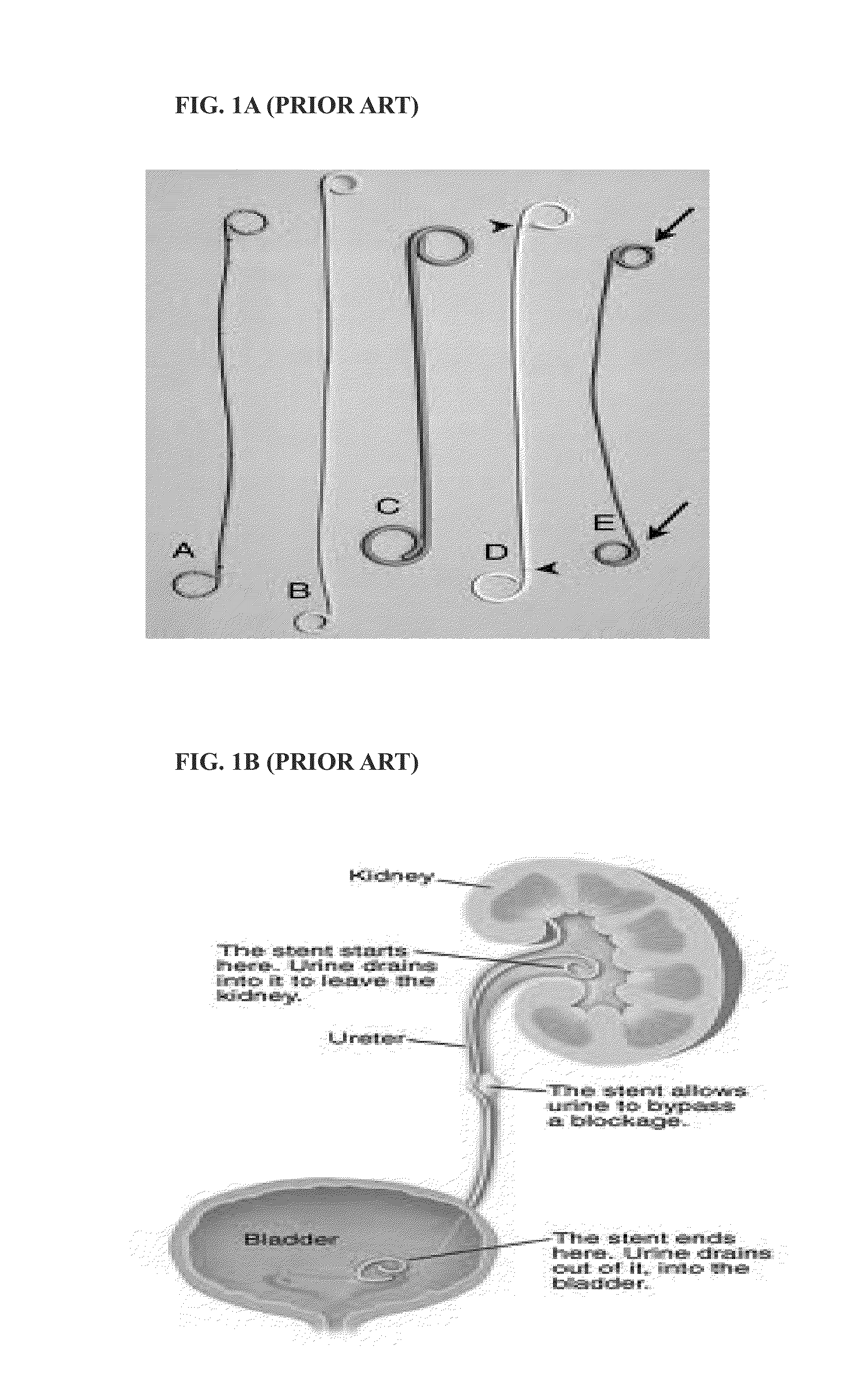
[0040]FIG. 1A shows prior art of ureteral stents. FIG. 1B shows the function of ureteral stents.

[0041]Typically, these stents are placed in a minimally invasive manner by passing the stent over a guide wire that has been positioned in the renal pelvis of the kidney. A pusher is used to advance the stent along the wire from the urethra to the bladder and subsequently into the ureter.

[0042]Other methods for stent placement are percutaneously where the physician accesses the ureter through the skin of patient using nephrostomy methods.

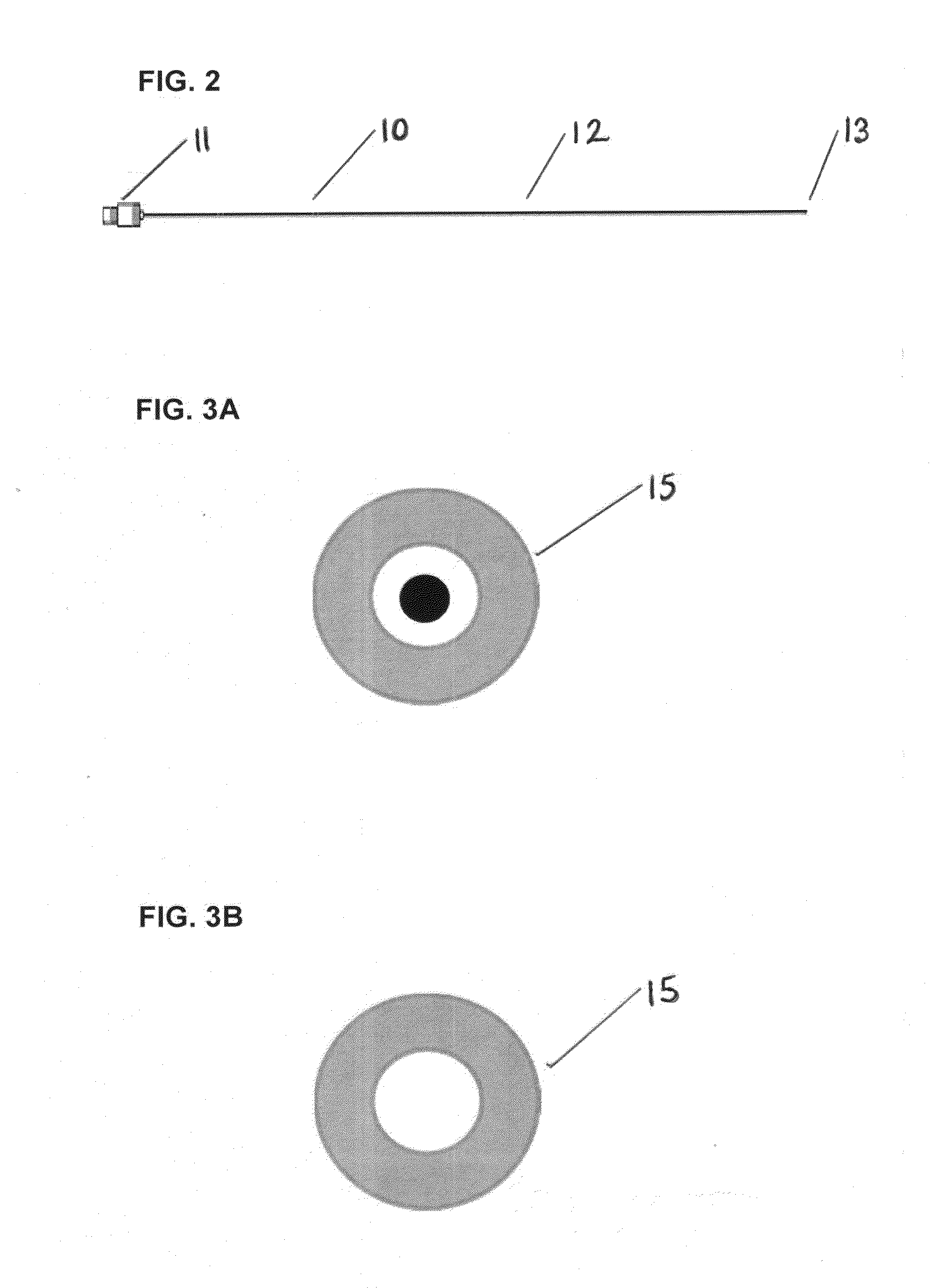
[0043]FIG. 2 displays the stent inserter and outer sheath. An embodiment of the design detailed in FIG. 2 is the small diameter of the outer sheath. The stent inserter reference number in FIG. 2 is 10. This significantly reduces trauma to the patient during the procedure and is specifically suitable for patients with ureters that are sized in the range from 0.3-0.7 mm (0.011-0.027″). Other physician benefits are the highly radiopaque properties of the ste...


PUM


Abstract

The invention is a stent designed for indwelling in a body, where its purpose would be to assist in the drainage of liquid from one part of the body to another. The stent is composed of a material that would typically be coiled to form a cylindrical shape along the length of the stent. Each end of the stent would typically be shaped to form a looped pigtail to prevent migration in the vessel. The stent can be used for minimally invasive procedures or alternatively, it could be placed percutaneously. This stent could be used in various parts of the body, such as the ureter, urethra, bile duct, liver, pancreas, vascular system and neurovascular system.

Description

REFERENCES CITEDU.S. Patent Documents[0001]U.S. Pat. No. 7,550,012 Jun. 23, 2009 LavelleU.S. Patent Documents[0002]U.S. Pat. No. 4,813,925 Mar. 21, 1989 Anderson & MaerzkeTECHNICAL FIELD[0003]The technical field of this invention is an implantable medical device. This invention is particularly suitable for use in veterinary or paediatric urological procedures.BACKGROUND OF THE INVENTION[0004]The placement of urology stents via minimally invasive techniques has continued to increase incrementally over the last decade. Both metal and plastic stents of various designs are being placed.[0005]A ureteral stent, for example, can be placed in certain circumstances to allow urine to drain from the kidney to the bladder and out of the body, when urine cannot flow through the ureter with ease.[0006]Recent advances in veterinary medicine have also enabled the placement of urology stents in animals. However, many or all of the urology stents being placed in veterinary medicine at present are pla...

Claims


Application Information

Patent Timeline
IPC IPC(8): A61F2/04
CPCA61F2002/047A61F2/04A61F2/88A61M27/008
Inventor MCDONOUGH, ARDLE, TOMAS
Owner MCDONOUGH ARDLE TOMAS
Learn More