Emitting device of wide-angle LED

a technology of wide-angle led and emitting device, which is applied in the direction of semiconductor devices for light sources, point-like light sources, lighting and heating apparatus, etc. it can solve the problems of more numbers, less light emission, and less relevance between primary and secondary optics, so as to reduce the number of construction needed, increase the intensity of the effect of illumination and heating, and reduce the number of prime costs

Inactive Publication Date: 2016-01-14
LUMENMAX OPTOELECTRONICS
View PDF23 Cites 6 Cited by
  • Summary
  • Abstract
  • Description
  • Claims
  • Application Information

AI Technical Summary

Benefits of technology

The present invention provides an emitting device of wide-angle LED that uses refraction of primary and secondary optics to extend the distance between each LED and reduce the number required for construction, thereby lowering costs. The device also enhances the lights through the primary optical process and concentrates them through the secondary optical process, resulting in improved quality. The device achieves this by emitting blue lights from a blue LED chip, which are then concentrated and heightened by a heat dissipating sink. The concentrated blue lights refract through a lens and turn into blue rays, which appear to cross and overlap, enabling the extension of the distance between each LED and reducing the number required for construction. The devices have also been found to enhance the lights in the primary optical process while spreading them out in the secondary optical process, resulting in a more uniform and bright emission.

Problems solved by technology

However, such optical design neglects the relevance between the primary and secondary optics.
But such concentration would require the distance between each LED arranged less than 1.5 cm, resulting more numbers needed for construction; or when the distance is longer than 1.5 cm, the lights would not emit uniformly and there would be dark areas.

Method used


Image

  • Emitting device of wide-angle LED
  • Emitting device of wide-angle LED
  • Emitting device of wide-angle LED

Examples


Embodiment Construction

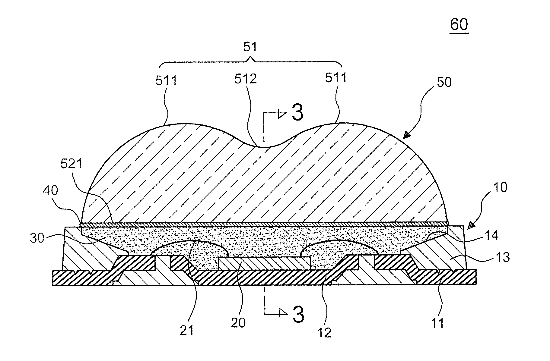
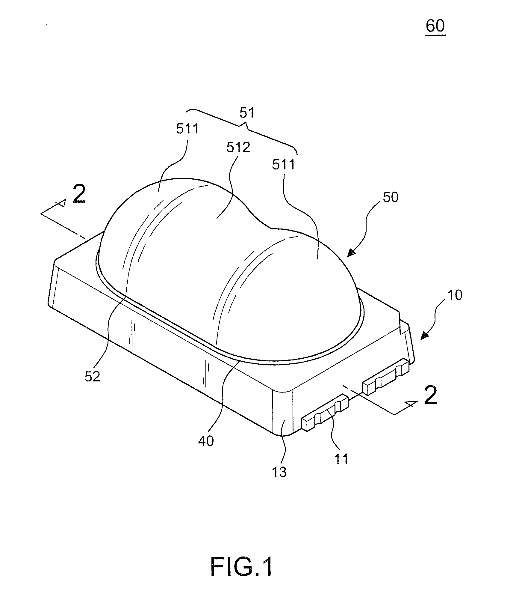
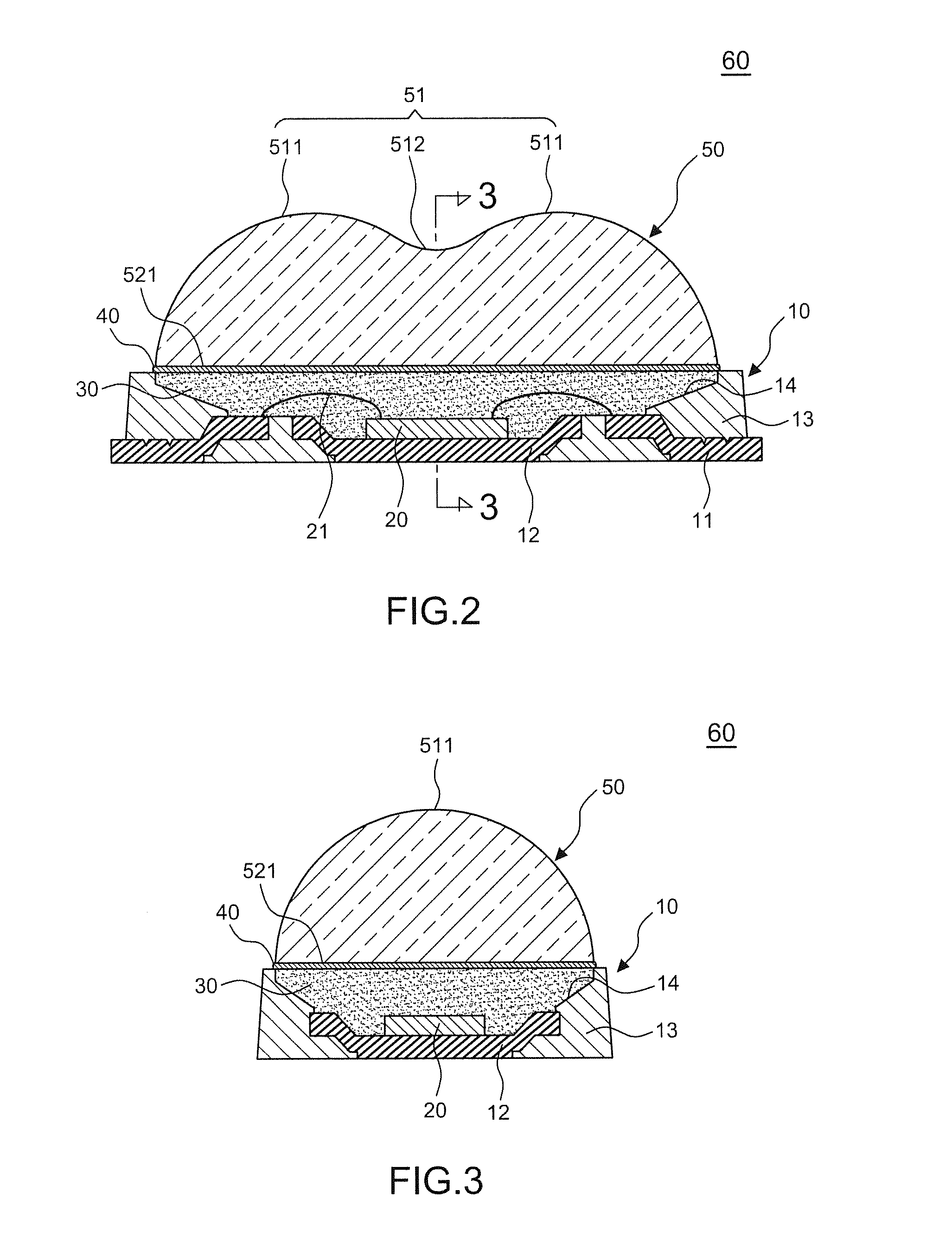
[0023]Referring to FIGS. 1-8, a preferred embodiment of the present invention comprises a wide-angle LED 60 including a base 10, a blue LED chip 20, a sealant body 30, and a lens 50, and an emitting device 90 including a least one wide-angle LED 60, a PCB 70, and a lighting tube 80.

[0024]The base 10 is formed by a pair of metal connecting base 11, a heat dissipating sink 12 and a rectangular housing 13. The metal connecting base pair 11 are arranged separately at the front and rear of the heat dissipating sink 12 and fixed together with it by the lower part of said rectangular housing 13; the upper thereof surrounds the heat dissipating sink 12 and forms a long concavity 14, keeping the underside of the metal connecting base 11 and the heat dissipating sink 12 exposed, and the top of the metal connecting base pair 11 partially exposed.

[0025]The blue LED chip 20 is arranged on the heat dissipating sink 12 and the electrodes thereof are connected separately to the metal connecting bas...


PUM


Abstract

An emitting device of wide-angle LED which comprises at least one wide-angle LED that emits at an angle between 140° and 160°, extending the distance between each wide-angle LED in the emitting device and reducing the number needed for construction. Also, the device has the lights emitted in uniformity and has no dark area. The luminance is improved as well. Besides, the wide-angle LED was applied twice packaging procedures to avoid the sealant body separating from the concavity due to damp environment. The emitting device of wide-angle LED therefore has improved quality and lower prime costs.

Description

BACKGROUND OF THE INVENTION [0001]1. Field of the Invention[0002]The present invention relates to an emitting device of wide-angle LED, particularly to one that has a wide-angle LED with wider emitting area and more intensive luminance, so that when engaging an emitting device the number needed for construction is reduced and the quality and effectiveness are improved.[0003]2. Description of the Related Art[0004]Nowadays LED technology is getting advanced and widely applied to emitting devices constructions, and the luminance quality of the devices lies in the optical design of LED structure. Basically the optical design can be divided into primary optics and secondary optics. The structures are as below.[0005]1. Primary optics: within the LED packaging, a colloid in shape of lens covers the LED chip and is fixed on a base, which can adjust the spreading or dispersing of lights; in other words, it functions as a first optical lens and the lights getting through it are in a fixed dir...

Claims


Application Information

Patent Timeline
Patent Type & Authority Applications(United States)
IPC IPC(8): H01L33/58F21K99/00F21V5/04F21V23/00F21V29/70H01L33/36H01L33/48H01L33/52H01L33/60H01L33/62H01L33/64
CPCH01L33/58F21V5/04F21V29/70F21V23/005F21K9/56H01L33/647F21Y2101/02H01L33/52H01L33/36H01L33/642H01L33/483H01L33/60H01L33/62H01L2224/48091H01L2224/48247H01L2924/181H01L2924/00014H01L2924/00012
Inventor YANG, HO-CHINGLIN, CHUN-TE
Owner LUMENMAX OPTOELECTRONICS
Why Eureka
Try Eureka