Heating device

a heating device and heating technology, applied in the direction of exothermal chemical reaction heat production, light and heating apparatus, electrochemical generators, etc., can solve the problems of carbon monoxide poisoning, time-consuming and energy-consuming, and the safety of heating devices, so as to improve the safety of use and facilitate the reaction, the activity of high-activity hydrogen is high

Inactive Publication Date: 2016-01-14
CORETRONIC
View PDF5 Cites 2 Cited by
  • Summary
  • Abstract
  • Description
  • Claims
  • Application Information

AI Technical Summary

Benefits of technology

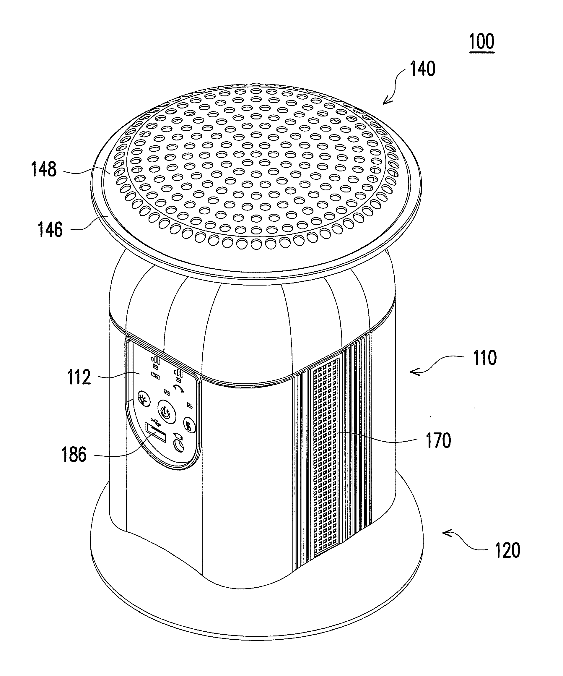
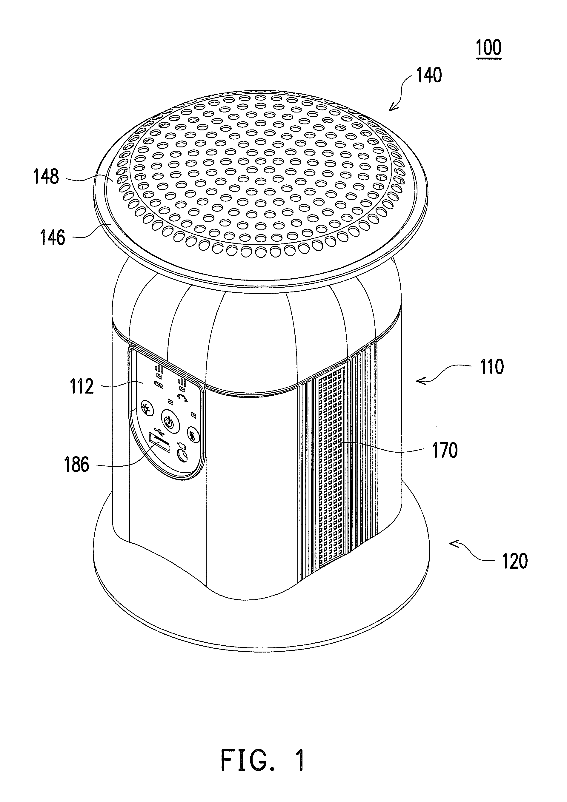
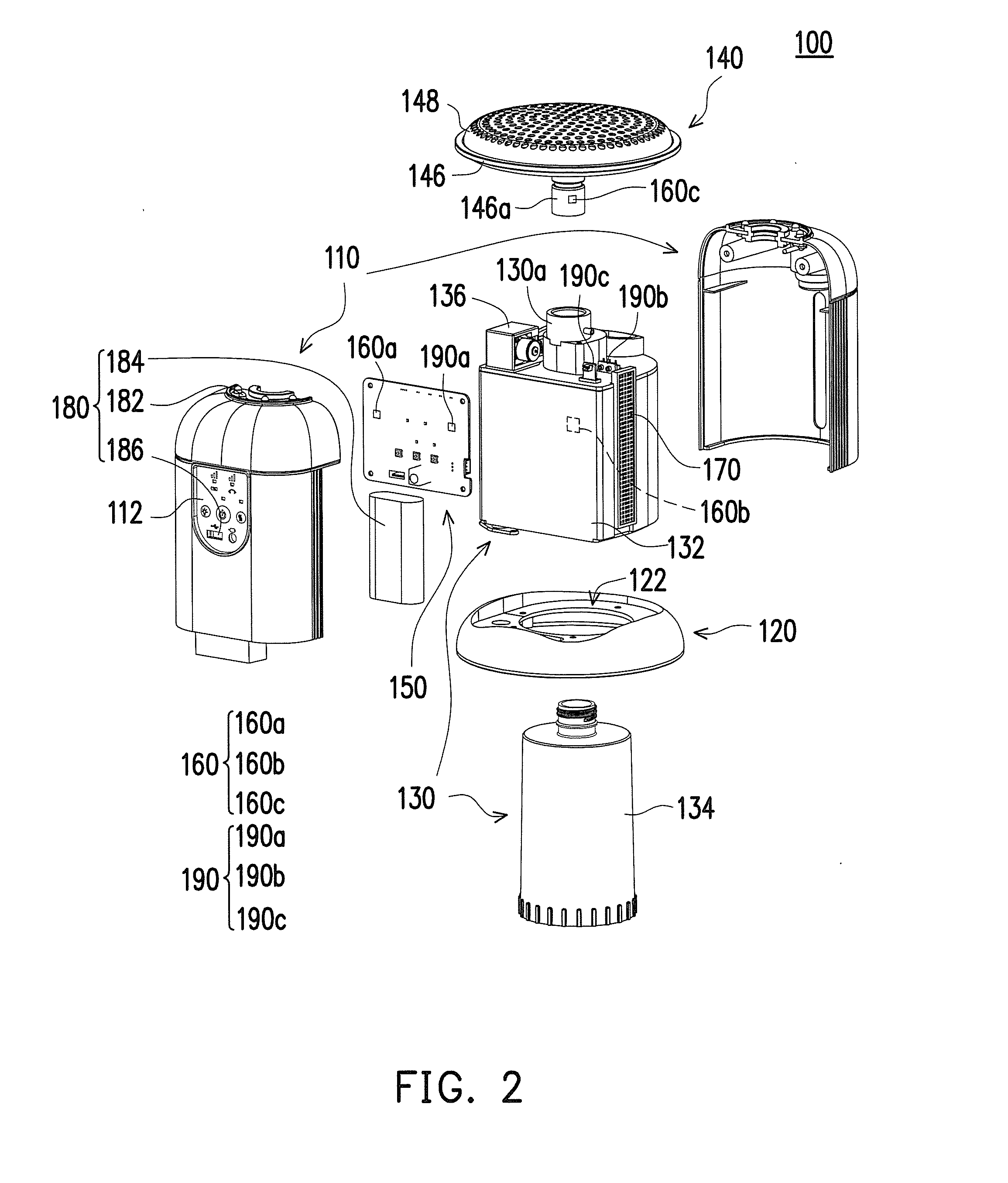
The invention is a heating device that uses hydrogen generated from a hydrogen generating unit to produce heat energy through an oxidation reaction with oxygen in the air. This type of heating device avoids the production of harmful carbon monoxide and flame, making it safer to use. The hydrogen generated from the hydrogen generating unit is quickly and effectively catalysed by a catalyst layer, resulting in more energy-efficient and time-saving usage. The driving element is used to move the liquid reactant towards the solid reactant, and a control unit automatically adjusts the flowing rate of the liquid reactant according to the heating quantity requirement, environmental temperature, and temperature of the hydrogen generating unit, making the heating device more convenient in usage. The safety protection module is included to detect abnormal usage states of the heating device and improve safety.

Problems solved by technology

Presently, portable heaters generally produce heat by burning gas, and such flame type heater has a risk of causing fire.
However, when the portable heater that generates the heat energy through the chemical reaction of the C3H8 is operated, the catalyst layer has to be pre-heated to about 150 degrees centigrade in order to effectively catalyse the C3H8 to react with oxygen, which is time-consuming and energy-consuming.
Moreover, besides vaporous water is generated from the chemical reaction between the C3H8 and the oxygen, carbon dioxide and carbon monoxide are also generated, and if such type of the portable heater is used in a confined space, it probably causes carbon monoxide poisoning.

Method used


Image

  • Heating device
  • Heating device
  • Heating device

Examples


Embodiment Construction

[0043]In the following detailed description of the preferred embodiments, reference is made to the accompanying drawings which form a part hereof, and in which are shown by way of illustration specific embodiments in which the invention may be practiced. In this regard, directional terminology, such as “top,”“bottom,”“front,”“back,” etc., is used with reference to the orientation of the Figure(s) being described. The components of the present invention can be positioned in a number of different orientations. As such, the directional terminology is used for purposes of illustration and is in no way limiting. On the other hand, the drawings are only schematic and the sizes of components may be exaggerated for clarity. It is to be understood that other embodiments may be utilized and structural changes may be made without departing from the scope of the present invention. Also, it is to be understood that the phraseology and terminology used herein are for the purpose of description an...


PUM

PropertyMeasurementUnit
heat energyaaaaaaaaaa
temperatureaaaaaaaaaa
electric energyaaaaaaaaaa

Abstract

A heating device including a heating unit, a temperature sensing module, a control unit, and a hydrogen generating unit having a first tank, a second tank, and a driving element is provided. The first tank contains a liquid reactant. The second tank contains a solid reactant. The driving element is connected between the first tank and the second tank, drives the liquid reactant to move from the first tank to the second tank, such that the liquid reactant reacts with the solid reactant to generate hydrogen. The heating unit is connected to the hydrogen generating unit and includes a catalyst layer. At least a part of hydrogen moves from the second tank to the heating unit and contacts the catalyst layer to react to generate heat energy. The control unit is electrically connected to the driving element, and controls the driving element according to a temperature of the heating device.

Description

CROSS-REFERENCE TO RELATED APPLICATION[0001]This application claims the priority benefit of China application serial no.[0002]201410333367.5, filed on Jul. 14, 2014. The entirety of the above-mentioned patent application is hereby incorporated by reference herein and made a part of this specification.BACKGROUND[0003]1. Technical Field[0004]The invention relates to a heating device, and particularly relates to a heating device capable of generating heat through chemical reaction of hydrogen.[0005]2. Related Art[0006]Presently, portable heaters generally produce heat by burning gas, and such flame type heater has a risk of causing fire. Another type of the portable heater uses a platinum group metal catalyst layer to catalyse hydrocarbon such as C3H8, etc. to produce chemical reaction with oxygen in the air, and generates heat energy required by the portable heater through the chemical reaction, and such non-flame type heater may reduce a chance of causing fire. However, when the port...

Claims


Application Information

Patent Timeline
Patent Type & Authority Applications(United States)
IPC IPC(8): F24V30/00H01M8/06
CPCF24J1/00H01M2250/40H01M8/0606F24V30/00H01M8/04208H01M8/0494H01M8/065H01M16/006Y02E60/10Y02E60/36Y02E60/50
Inventor LU, HSUAN-YIWANG, CHUNG-PINGLIN, YU-HSIANGYEN, YI-WEI
Owner CORETRONIC
Why Eureka
Try Eureka