
Hydraulic Pressure Supply System of Automatic Transmission

a technology of automatic transmission and hydraulic pressure supply, which is applied in the direction of fluid pressure control, process and machine control, instruments, etc., can solve the problem of not being able to control the electric motor at an optimal rpm, and achieve the effect of optimizing the flow, minimizing the loss of unnecessary flow, and improving transmission efficiency

Active Publication Date: 2016-01-07
HYUNDAI MOTOR CO LTD
View PDF15 Cites 3 Cited by
  • Summary
  • Abstract
  • Description
  • Claims
  • Application Information

AI Technical Summary

Benefits of technology

The present invention relates to a hydraulic pressure supply system for an automatic transmission that uses two oil pumps and one pressure sensor to optimize flow and minimize unnecessary flow loss at high RPM, thereby improving transmission efficiency. The system controlling the electric motor uses information provided by the pressure sensor to minimize flow loss and improve transmission efficiency. The technical effect of this invention is to enhance the performance and efficiency of hydraulic pressure supply systems for automatic transmissions.

Problems solved by technology

However, in a hydraulic pressure supply system according to the related art, since only whether or not a target pressure is reached is detected without detecting an excess flow, it is impossible to control the electric motor at an optimal RPM.

Method used


Image

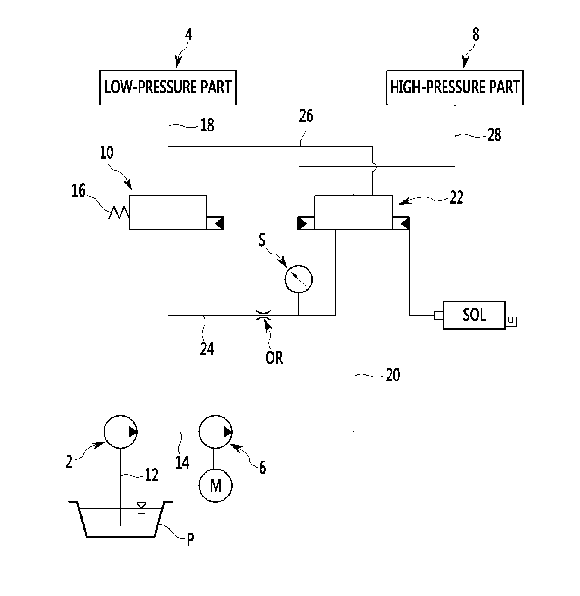
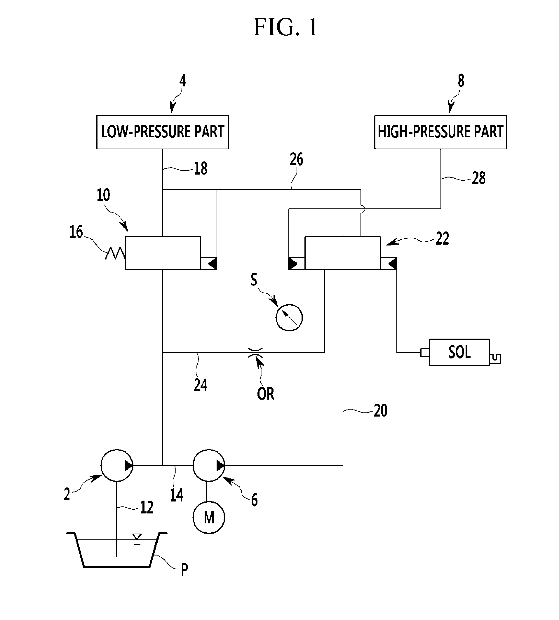
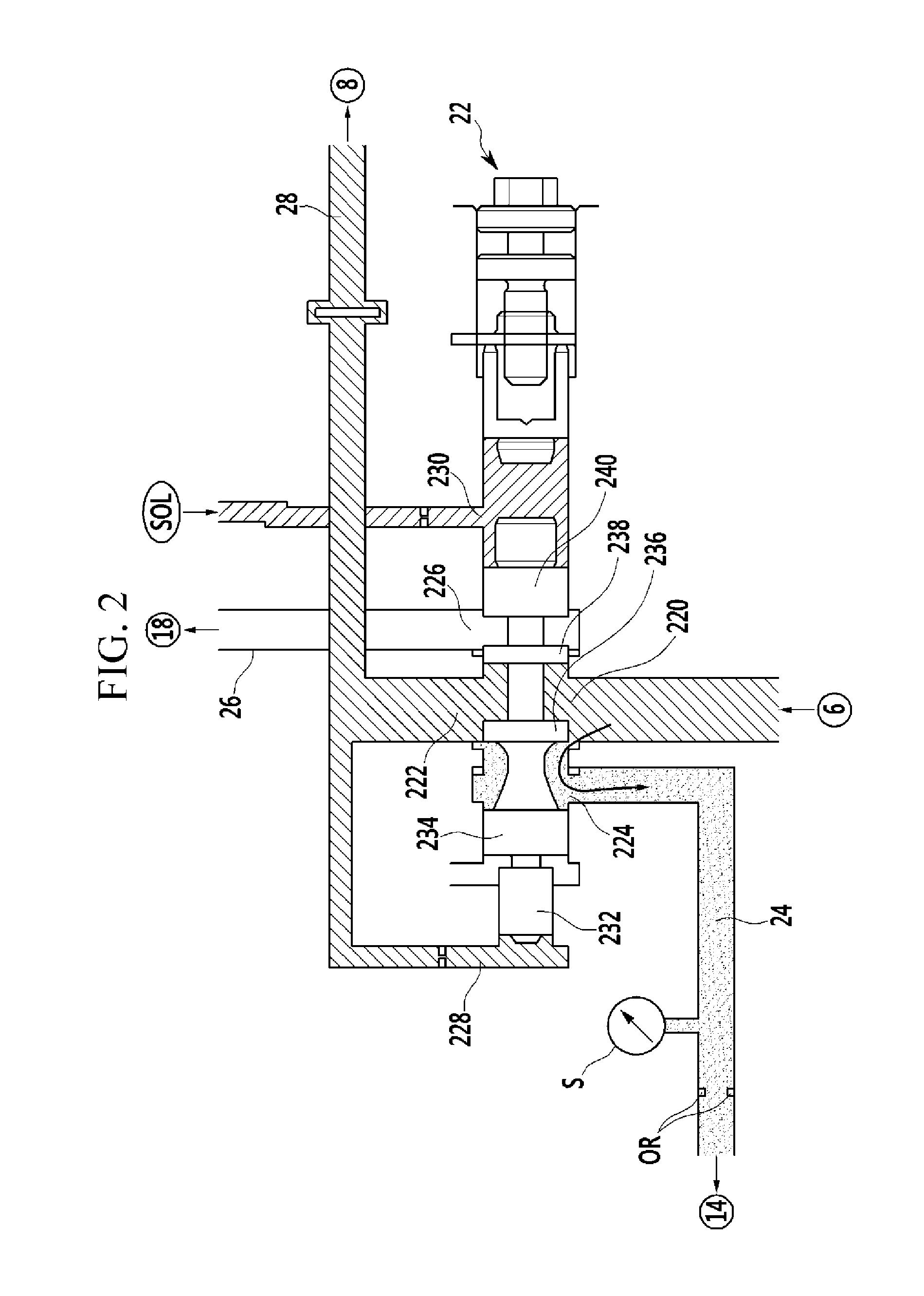
  • Hydraulic Pressure Supply System of Automatic Transmission
  • Hydraulic Pressure Supply System of Automatic Transmission
  • Hydraulic Pressure Supply System of Automatic Transmission

Examples


Embodiment Construction

[0023]Reference will now be made in detail to various embodiments of the present invention(s), examples of which are illustrated in the accompanying drawings and described below. While the invention(s) will be described in conjunction with exemplary embodiments, it will be understood that the present description is not intended to limit the invention(s) to those exemplary embodiments. On the contrary, the invention(s) is / are intended to cover not only the exemplary embodiments, but also various alternatives, modifications, equivalents and other embodiments, which may be included within the spirit and scope of the invention as defined by the appended claims.

[0024]Hereinafter, exemplary embodiment of the present invention will be described in detail with reference to the accompanying drawings.

[0025]However, in order to clarify the present invention, parts that are not connected with the description will be omitted.

[0026]The use of the terms first, second, etc. are used to distinguish ...


PUM


Abstract

A hydraulic pressure supply system of an automatic transmission may include a low-pressure oil pump generating low hydraulic pressure while being driven by an engine to exhaust the low hydraulic pressure to a first low-pressure channel, a high-pressure oil pump raising a portion of the hydraulic pressure in the first low-pressure channel to a high pressure while being driven by an electric motor to exhaust the hydraulic pressure to a first high-pressure channel, a low-pressure regulator valve controlling the hydraulic pressure while exhausting a portion of the hydraulic pressure to supply the controlled hydraulic pressure to a low-pressure part through a second low-pressure channel, and a high-pressure regulator valve controlling the hydraulic pressure while re-circulating a portion of the hydraulic pressure to the low-pressure part through single or two re-circulation channels according to the pressure to supply the controlled hydraulic pressure to a high-pressure part through the second high-pressure channel.

Description

CROSS-REFERENCE TO RELATED APPLICATION[0001]The present application claims priority to and the benefit of Korean Patent Application No. 10-2014-0082015 filed on Jul. 1, 2014, the entire contents of which is incorporated herein for all purposes by this reference.BACKGROUND OF THE INVENTION[0002]1. Field of the Invention[0003]The present invention relates to a hydraulic pressure supply system of an automatic transmission. More particularly, the present invention relates to a hydraulic pressure supply system of an automatic transmission capable of detecting a pressure exhausted from a high-pressure regulator valve to control an electric motor at an optimal revolution per minute (rpm).[0004]2. Description of Related Art[0005]Recently, as oil price has increased and exhaust gas emission regulations, or the like, have gradually been strengthened in the world, auto-makers are going-all out to develop a technology capable of improving fuel efficiency by an eco-friendly method.[0006]Fuel eff...

Claims


Application Information

Patent Timeline
Patent Type & Authority Applications(United States)
IPC IPC(8): F16H61/00F16K11/06G05D16/20
CPCF16H61/0031F16K11/06G05D16/2013F16H61/0276F16H2061/0037B60W10/10F16H61/00F16H61/04F16H61/4008F16K11/07
Inventor SON, HYUNJUNJO, SEHWAN
Owner HYUNDAI MOTOR CO LTD
Learn More