Pump including a shield for protecting a pump wheel against a coolant leak along the hub of the wheel

a technology for pump wheels and shields, which is applied in the direction of liquid fuel engines, greenhouse gas reduction, nuclear elements, etc., can solve the problems of deterioration of shafts and pump wheels, still observed traces of contact wear on the shaft and the pump wheel, etc., and achieve the effect of reducing the maintenance cost of the primary pump and minimizing contact wear

Inactive Publication Date: 2016-01-07
AREVA NP SAS
View PDF3 Cites 0 Cited by
  • Summary
  • Abstract
  • Description
  • Claims
  • Application Information

AI Technical Summary

Benefits of technology

[0017]One aim of the invention is therefore to reduce the maintenance costs of the primary pump, in particular by minimizing the contact wear between the pump wheel and the driveshaft.

Problems solved by technology

However, such a system is not fully satisfactory.
In fact, despite the presence of this system for causing water of the primary circuit to flow in the first end segment of the shaft, traces of deterioration of the shaft and the pump wheel by contact wear are still observed.

Method used


Image

  • Pump including a shield for protecting a pump wheel against a coolant leak along the hub of the wheel
  • Pump including a shield for protecting a pump wheel against a coolant leak along the hub of the wheel
  • Pump including a shield for protecting a pump wheel against a coolant leak along the hub of the wheel

Examples


Embodiment Construction

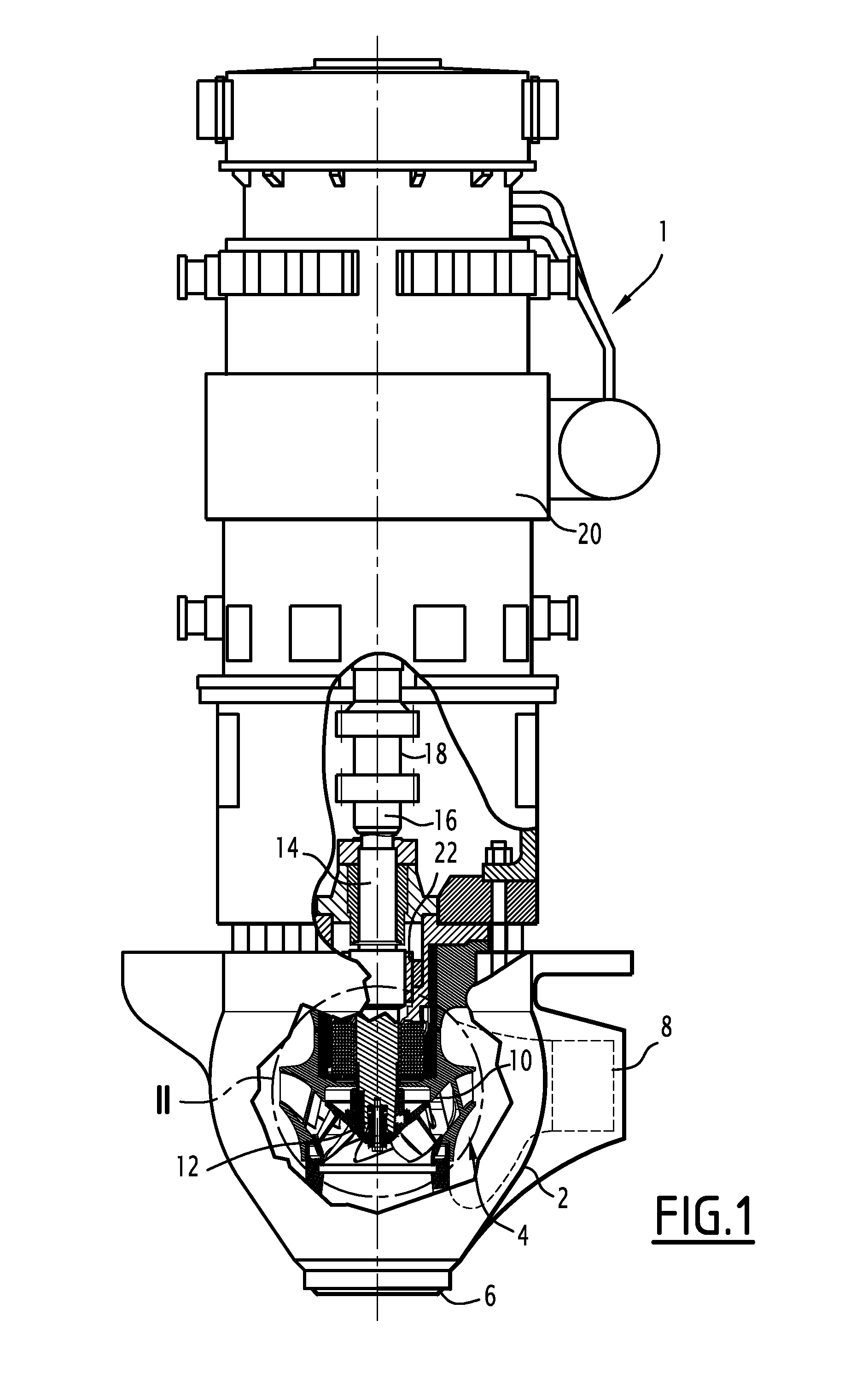
[0040]The pump 1, shown in FIG. 1, is a primary pump of a pressurized water nuclear reactor. This pump 1 is suitable for causing a heat-transport fluid to flow, in this case pressurized water at a temperature close to 300° C., in a fluid circuit, in the case at hand the primary circuit of the nuclear reactor.

[0041]To that end, the primary pump 1 includes a pump body 2 delimiting a chamber 4, or volute, for causing a heat-transport fluid to flow, fluidly connected by means of a first tubing 6 to a first line of the primary circuit and by a second tubing 8 to a second line of the primary circuit, between which the pump 1 establishes a certain pumping pressure to cause the heat-transport fluid to flow.

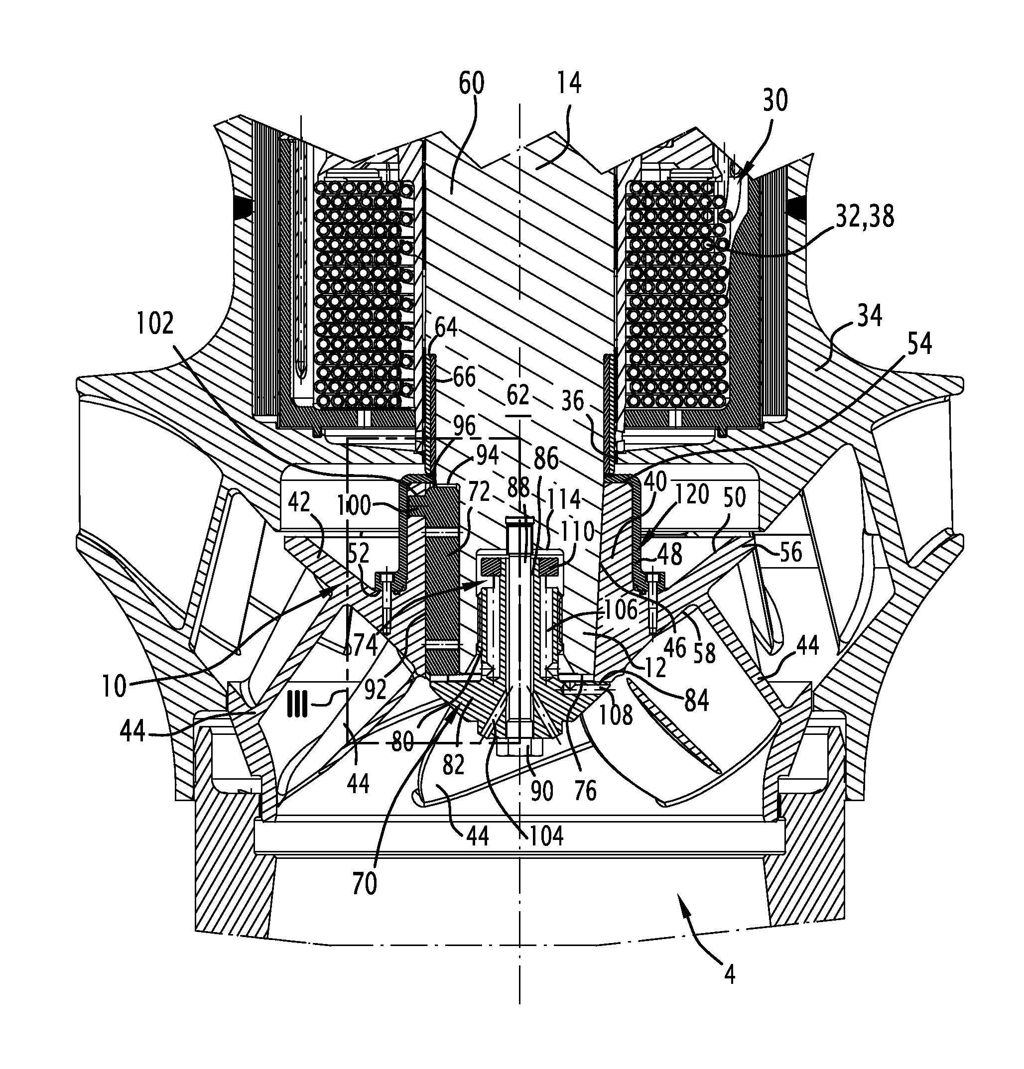
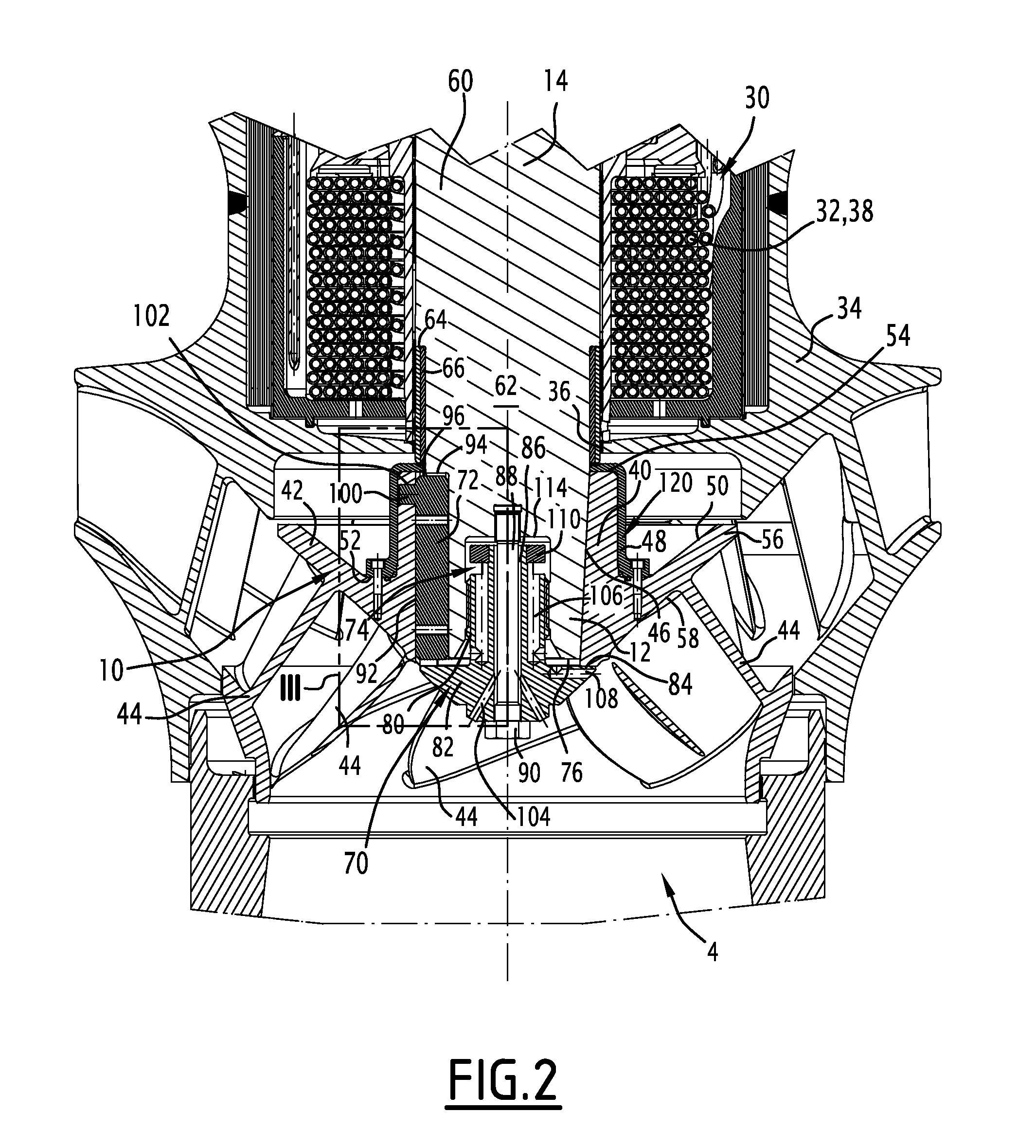
[0042]The pump 1 further includes a pump wheel 10 for establishing the pumping pressure between the first and second tubings 6, 8. This pump wheel 10 is bound on a lower axial end segment 12 of a driveshaft 14 oriented substantially vertically and the upper axial end segment 16 of which i...


PUM


Abstract

A pump is provided. The pump includes a flow chamber for the heat-transport fluid, a pump wheel which is placed entirely in the flow chamber and which comprises a hub, a shaft for rotating the pump wheel, having an axial end section rigidly connected to the pump wheel and fitted in the hub of the pump wheel, a motor for rotating the shaft around its axis, and means for causing a coolant for cooling the driveshaft to flow, at a temperature lower than that of the heat-transport fluid, along the driveshaft. The pump also includes a shield for protecting the pump wheel against a coolant leak along an outer peripheral surface of the hub of the pump wheel, the protective shield being attached to the pump wheel.

Description

[0001]The present invention relates to a pump for causing a heat-transport fluid to flow in a fluid circuit, of the type comprising:[0002]a flow chamber for the heat-transport fluid,[0003]a pump wheel which is placed entirely in the flow chamber and which comprises a hub,[0004]a shaft for rotating the pump wheel, having an axial end section rigidly connected to the pump wheel and fitted in the hub of the pump wheel,[0005]a motor for rotating the shaft around its axis, and[0006]means for causing a coolant for cooling the driveshaft to flow, at a temperature lower than that of the heat-transport fluid, along the driveshaft.BACKGROUND[0007]In nuclear reactors cooled by pressurized water, the pressurized cooling water of the nuclear reactor is made to flow in the cooling circuit of the core of the nuclear reactor, or primary circuit, by a pump, called primary pump, and including a single pump wheel submerged in the pressurized water filling the primary circuit.[0008]The pump wheel is dr...

Claims


Application Information

Patent Timeline
Patent Type & Authority Applications(United States)
IPC IPC(8): F04D29/58F04D7/08F04D13/06
CPCF04D29/5806F04D13/06F04D7/08F04D29/106F04D29/20F04D29/588G21C15/243Y02E30/30
Inventor PHILIPPART, OLIVIER
Owner AREVA NP SAS
Why Eureka
Try Eureka