
Portable Vehicle Battery Jump Start Apparatus with Safety Protection and Jumper Cable Device Therefor

a technology for vehicle batteries and jump-starting devices, which is applied in the directions of battery overheat protection, safety/protection circuits, transportation and packaging, etc., can solve problems such as battery sparking and potential damage, and/or bodily injury

Active Publication Date: 2016-01-07
THE NOCO
View PDF14 Cites 49 Cited by
  • Summary
  • Abstract
  • Description
  • Claims
  • Application Information

AI Technical Summary

Benefits of technology

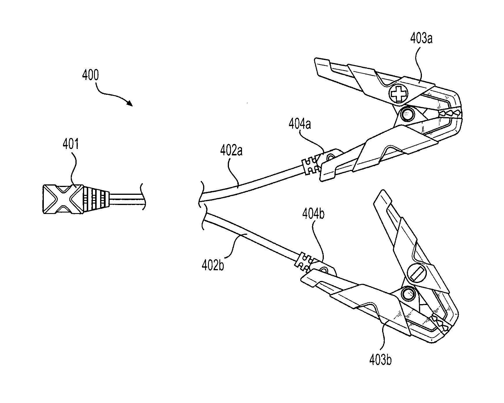
This patent describes a device for jump starting a vehicle engine using an internal power supply, such as a rechargeable lithium ion battery pack. The device has a vehicle battery isolation sensor and a reverse polarity sensor to detect the presence of a battery and its proper polarity connection. The device also includes a power FET switch and a microcontroller to activate the switch in response to signals from the sensors. Additionally, a jumper cable device is provided with a plug to connect to a handheld battery charger booster device. This device allows for easy and safe jump starting of a vehicle engine using a portable battery charger.

Problems solved by technology

Problems with the prior art arose when either the jumper terminals or clamps of the cables were inadvertently brought into contact with each other while the other ends were connected to a charged battery, or when the positive and negative terminals were connected to the opposite polarity terminals in the vehicle to be jumped, thereby causing a short circuit resulting in sparking and potential damage to batteries and / or bodily injury.
While the prior art attempted solutions to the abovementioned problems as discussed above, each of the prior art solutions suffers from other shortcomings, either in complexity, cost or potential for malfunction.

Method used


Image

  • Portable Vehicle Battery Jump Start Apparatus with Safety Protection and Jumper Cable Device Therefor
  • Portable Vehicle Battery Jump Start Apparatus with Safety Protection and Jumper Cable Device Therefor
  • Portable Vehicle Battery Jump Start Apparatus with Safety Protection and Jumper Cable Device Therefor

Examples


Embodiment Construction

[0020]FIG. 1 is a functional block diagram of a handheld battery booster according to one aspect of the invention. At the heart of the handheld battery booster is a lithium polymer battery pack 32, which stores sufficient energy to jump start a vehicle engine served by a conventional 12 volt lead-acid or valve regulated lead-acid battery. In one example embodiment, a high-surge lithium polymer battery pack includes three 3.7V, 2666 mAh lithium polymer batteries in a 3S1P configuration. The resulting battery pack provides 11.1V, 2666Ah (8000 Ah at 3.7V, 29.6 Wh). Continuous discharge current is 25 C (or 200 amps), and burst discharge current is 50 C (or 400 amps). The maximum charging current of the battery pack is 8000 mA (8 amps).

[0021]A programmable microcontroller unit (MCU) 1 receives various inputs and produces informational as well as control outputs. The programmable MCU 1 further provides flexibility to the system by allowing updates in functionality and system parameters, w...


PUM


Abstract

A handheld device for jump starting a vehicle engine includes a rechargeable lithium ion battery pack and a microcontroller. The lithium ion battery is coupled to a power output port of the device through a FET smart switch actuated by the microcontroller. A vehicle battery isolation sensor connected in circuit with positive and negative polarity outputs detects the presence of a vehicle battery connected between the positive and negative polarity outputs. A reverse polarity sensor connected in circuit with the positive and negative polarity outputs detects the polarity of a vehicle battery connected between the positive and negative polarity outputs, such that the microcontroller will enable power to be delivered from the lithium ion power pack to the output port only when a good battery is connected to the output port and only when the battery is connected with proper polarity of positive and negative terminals.

Description

BACKGROUND OF THE INVENTION[0001]The present invention relates generally to apparatus for jump-starting a vehicle having a depleted or discharged battery. Prior art devices are known, which provide either a pair of electrical connector cables that connect a fully-charged battery of another vehicle to the engine start circuit of the dead battery vehicle, or portable booster devices which include a fully-charged battery which can be connected in circuit with the vehicle's engine starter through a pair of cables.[0002]Problems with the prior art arose when either the jumper terminals or clamps of the cables were inadvertently brought into contact with each other while the other ends were connected to a charged battery, or when the positive and negative terminals were connected to the opposite polarity terminals in the vehicle to be jumped, thereby causing a short circuit resulting in sparking and potential damage to batteries and / or bodily injury.[0003]Various attempts to eliminate the...

Claims


Application Information

Patent Timeline
Patent Type & Authority Applications(United States)
IPC IPC(8): B60L11/18H02J7/00
CPCH02J7/0054B60L11/1816H02J7/0047H02J7/0034H02J7/0029B60L53/14H02J1/122H02J7/0048H02J7/342H02J2310/46Y02T10/7072Y02T90/14H02J7/00302H02J7/00309H02J7/00306H02J7/00
Inventor NOOK, JONATHAN LEWISNOOK, WILLIAM KNIGHTSTANFIELD, JAMES RICHARDUNDERHILL, DEREK MICHAEL
Owner THE NOCO
Learn More