
Ink curing apparatus

Active Publication Date: 2016-01-07
GEWEC
View PDF5 Cites 1 Cited by
  • Summary
  • Abstract
  • Description
  • Claims
  • Application Information

AI Technical Summary

Benefits of technology

This patent aims to improve UV lamps used for curing ink by making them easier and safer to change, while also reducing the time and cost of maintaining the UV curing apparatus. The technical effect is to provide a more efficient and reliable ink curing solution.

Problems solved by technology

UV lamps for use in ink curing machines are run at high intensities and consequently have a limited life span such that lamps have to be frequently cleaned and changed.
Manoeuvring both ends of the lamp in this way often makes maintenance and repair difficult for a single person to complete; that is, safely inserting the lamp into the housing often requires two people.
It has been found that manoeuvring the second end of the lamp to connect the lamp causes the first end of the lamp to be displaced from its desired position.
There is a significant risk that this displacement of the first end of the lamp can cause the first lamp end to snap from the glass tube or be otherwise damaged whilst a user is endeavouring to connect the second end of the lamp.

Method used


Image

  • Ink curing apparatus
  • Ink curing apparatus
  • Ink curing apparatus

Examples


Embodiment Construction

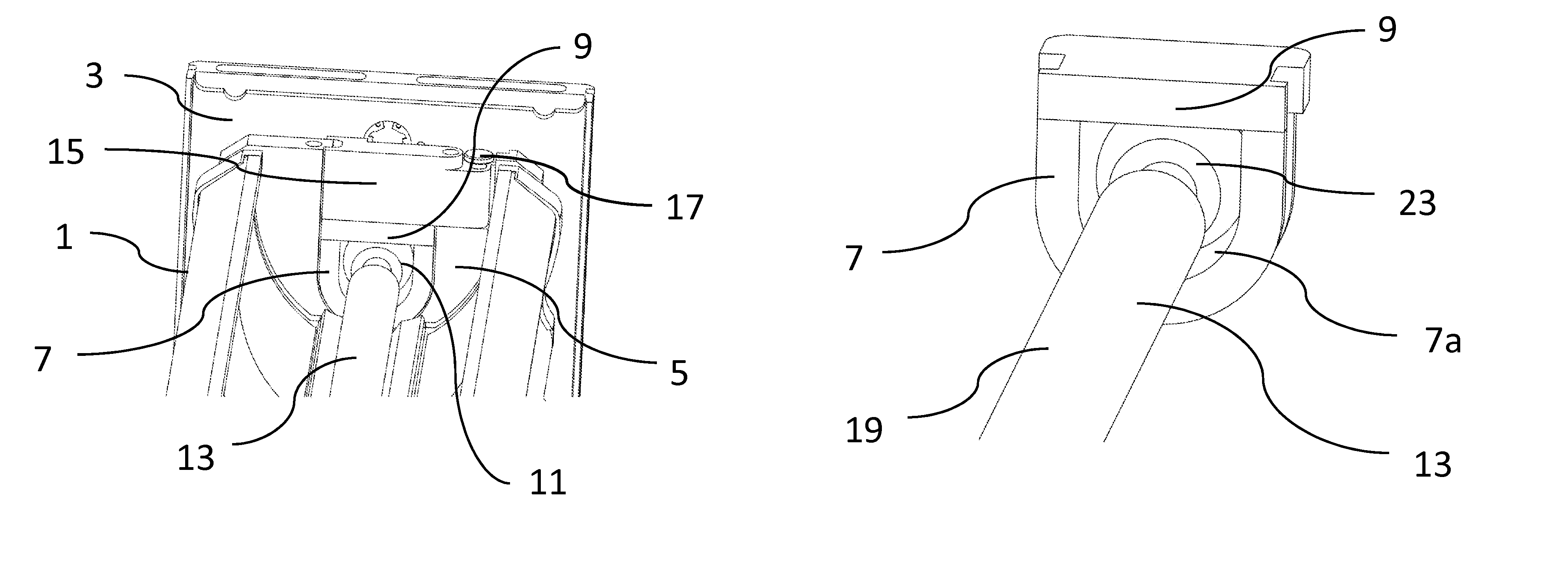
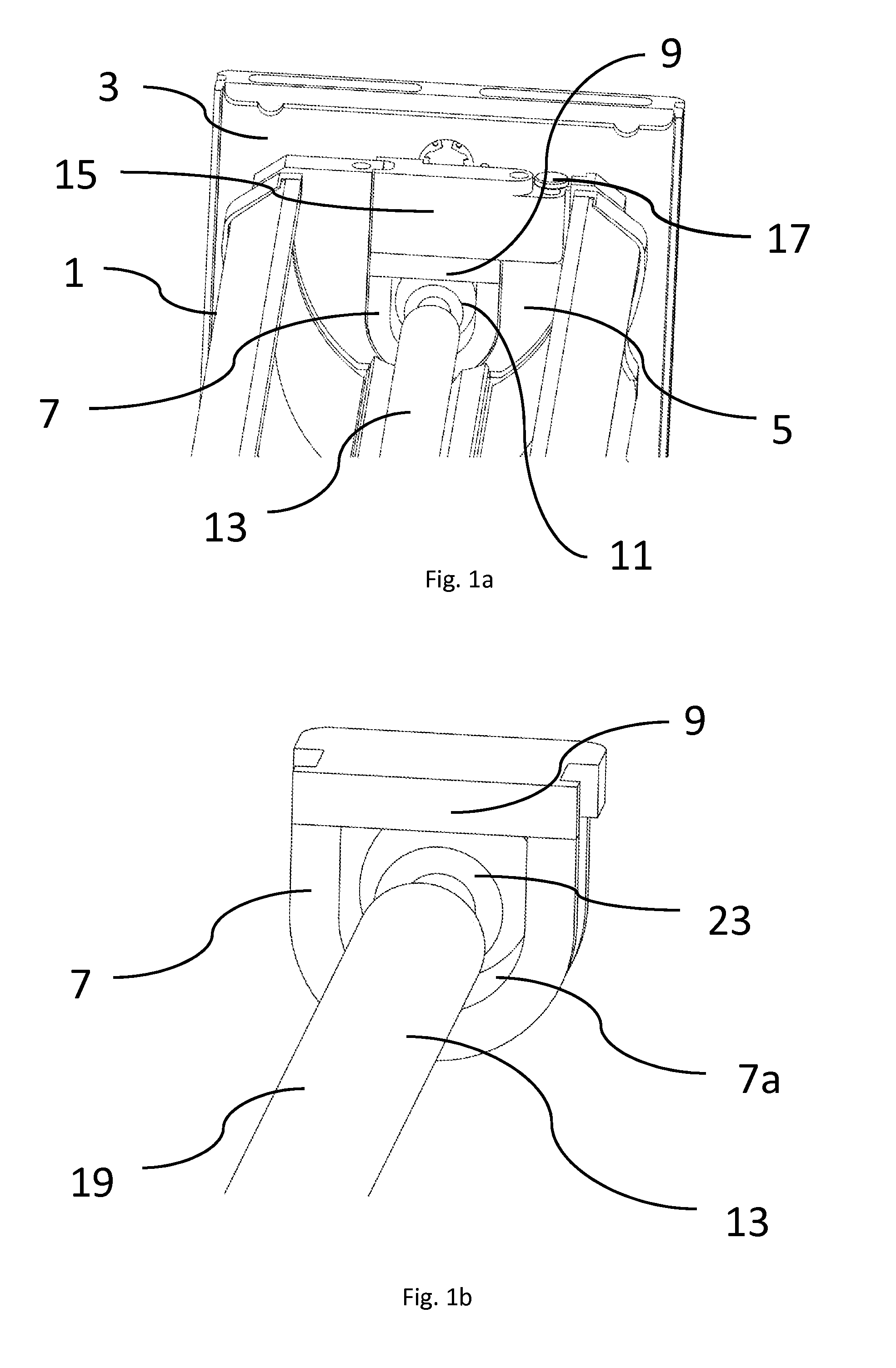
[0028]Referring to FIG. 1a, the ink curing apparatus comprises a lamp housing 1, which is an interchangeable “cassette”3 for use in ultra violet (UV) print curing. Each end of the lamp housing 1 has an aluminium end plate 5. A second endplate at the opposing end of the lamp housing 1 is not shown in FIG. 1. The cassette 3 comprises a lamp fitting 7, 9 having a curved ceramic body 7 fixed to the cassette 3 and a removable ceramic closure member 9 between which an opening 11 is defined. The cassette 3 is provided with a connection means (not shown) for connecting and disconnecting a UV lamp 13 to and from the power connected to the housing 1. For example, the connection means is a plug / socket arrangement allowing a lamp 13 to be connected into cassette 3 using a “push-fit” connection. The lamp 13 has a rod-shaped, hollow main body made, for example, of quartz. The main body has located therein chemical compounds to provide ultra violet (UV) radiation when an electrical source is appli...


PUM


Abstract

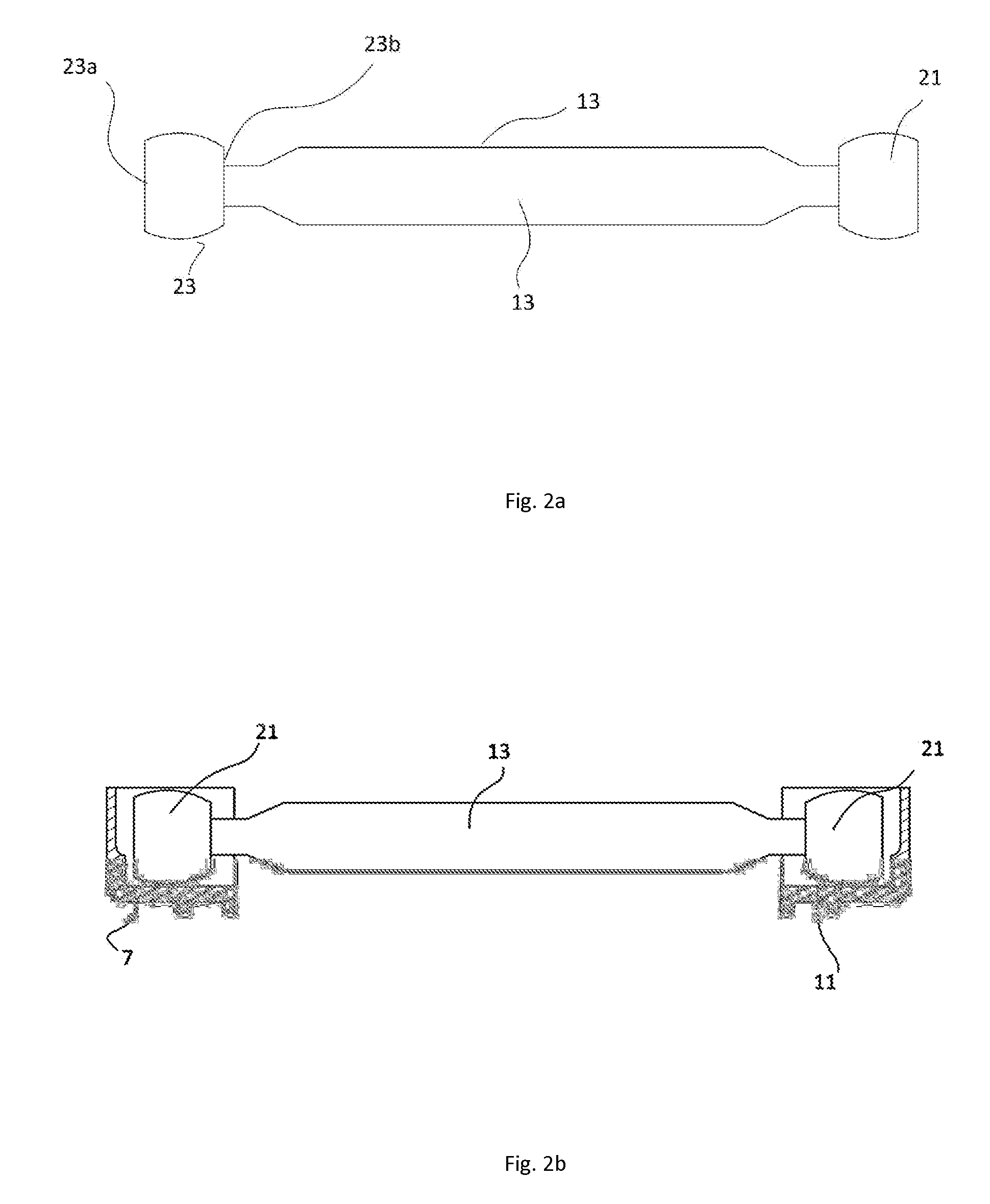
An ink curing apparatus comprising a lamp housing with a lamp fitting for a lamp terminal of a UV lamp at each opposing end, wherein at least one of the lamp fittings is non-conducting and has a non-conducting lamp terminal seat which has a concave profile for receiving a substantially spherical lamp terminal end piece; whereby, in use during the fitting or removal of a lamp, the at least one lamp fitting allows a lamp terminal end piece to rotate about multiple axes, whilst being retained substantially in position at the lamp fitting.

Description

CROSS REFERENCE TO RELATED APPLICATIONS[0001]This application is based upon and claims the benefit of priority from GB1411699.0 filed on Jul. 1, 2014, the contents of which are incorporated herein by reference.BACKGROUND OF THE INVENTION[0002]The present invention relates to a UV lamp. More specifically, the invention relates to a UV lamp for use with ink curing apparatus used commonly in the printing industry.[0003]Lamps used in ink curing apparatus generally comprise a glass tube with an electrode extending into each end of the lamp tube. It is common for the terminal assembly at each end of the tube to be pinch sealed and received within a small ceramic block into which the free end of each electrode also extends. A wire extends out of the ceramic block for connection to the electricity supply used to power the lamp. Existing lamp terminal arrangements are connected to the ink curing apparatus using a threaded screw clamped with a nut. The applicant's earlier UK patent applicatio...

Claims


Application Information

Patent Timeline
IPC IPC(8): B05D3/06
CPCB05D3/067B41F23/0409B41F23/0453B41J11/00214
Inventor RAE, MALCOLMHICKS, JAMES
Owner GEWEC
Learn More