
Safety stirrup with detachable elastic portion

a safety stirrup and elastic portion technology, applied in the direction of stirrups, fastening devices, domestic applications, etc., can solve the problems of unreliable, unintentional sliding of the rubber ring off the hook, no support for the foot in the direction, etc., to add to the comfort of experienced riders, easy to be bent outwards, and easy to leave the stirrup

Inactive Publication Date: 2005-04-14
SJOSWARD ROLF
View PDF9 Cites 19 Cited by
  • Summary
  • Abstract
  • Description
  • Claims
  • Application Information

AI Technical Summary

Benefits of technology

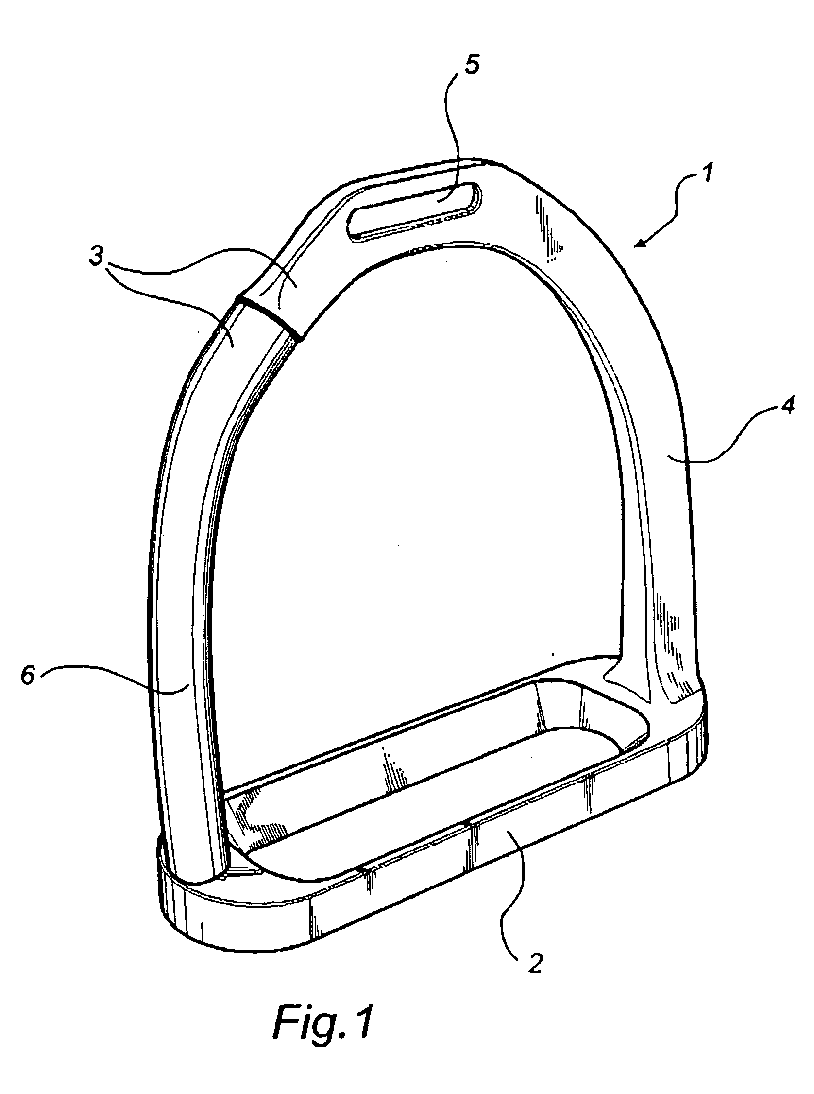
[0006] The inventive stirrup comprises a base part and stirrup arms, for use while riding, the stirrup arm which in use is the outer arm, seen from the horse, being elastic at least along a portion. Furthermore, the elastic portion is arranged on the outer stirrup arm in such a manner that the elastic portion is detachable along the extent of the outer stirrup arm at least at one end of the elastic portion. The elastic portion and the remaining part of the outer stirrup arm are thus disconnectible when the elastic portion is subjected to tractive force, relative to the extension of the stirrup arm, exceeding a certain threshold value. The above-mentioned tractive force arises in use by the rider's foot applying a pressure to the side of the elastic portion which thus is pulled out of its position, i.e. out of the connection to the remaining part of the stirrup arm. A great advantage of this solution thus is that the elastic portion is only pulled out of its position and, thus, can be put back again.
[0009] Conveniently the elastic portion is arched when positioned in the stirrup, i.e. it constitutes a fairly large part of the stirrup arm. As a result of the arched shape, the elastic portion offers resistance to being bent towards the rider's foot and is consequently easier to be bent outwards. This thus protects the foot from being subjected to loads from the outside, and at the same time the foot can more easily leave the stirrup when the elastic portion is “prebent” away from the stirrup.
[0010] The base part of the stirrup is preferably angled relative to the stirrup arms in such a manner that, in use, it guides the rider's foot to a position where the heel is located at a slightly lower level compared to the front part of the foot. This requires, of course, the base part to have a certain extent in the longitudinal direction of the foot. Such angling helps especially beginners to obtain a correct riding posture and at the same time it adds to the comfort of experienced riders since they can use the entire base part for the foot to rest on instead of the sole being in contact only with the rear edge of the stirrup, especially when boots with a rigid sole is used.
[0011] Moreover the base part is suitably frame-shaped, i.e. it is hollow seen from above and from below. This saves material, but also allows in an easy way a rubber pad to be fixed to the base part. The rubber pad or tread is suitably made of a material that produces high friction against the sole of the rider's boot. The higher friction, the better control of the location of the stirrup relative to the rider's foot.

Problems solved by technology

A problem with this type of stirrup, however, is that there is no support for the foot in the direction in the stirrup where this rubber ring is arranged.
When moving the foot vigorously in the stirrup there is no support and, thus, the rubber ring can unintentionally slide off the hook.
Most of these stirrups comprise different kinds of more or less advanced functions that are not always reliable.
As a result of many parts being articulated to each other there is a risk of such joints jamming if, for instance, earth or clay sticks to the stirrup, which frequently happens especially where the ground is wet as the rider mounts his horse.
The more complicated such constructions, the more expensive they are as a rule.

Method used


Image

  • Safety stirrup with detachable elastic portion
  • Safety stirrup with detachable elastic portion
  • Safety stirrup with detachable elastic portion

Examples


Embodiment Construction

[0018] The stirrup 1 in FIG. 1 comprises a base part 2 and two stirrup arms 3, 4 and also an opening 5 by which the stirrup 1 is suspended from a stirrup leather 7 (see FIG. 2a). One stirrup arm 3 has an elastic portion 6, preferably a rubber tube. The stirrup 1, except the elastic portion 6, is preferably made of steel.

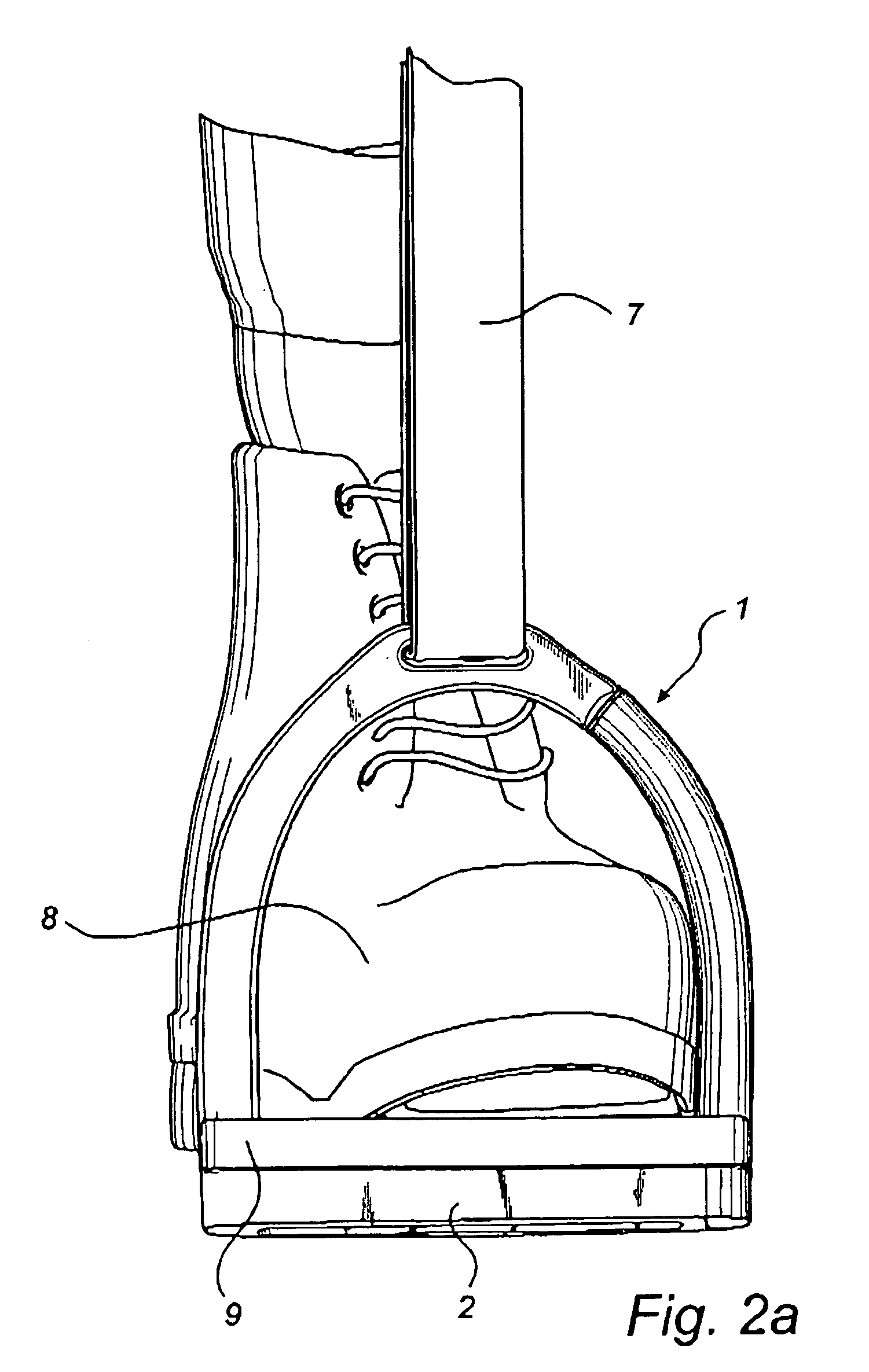
[0019]FIG. 2a shows the stirrup 1 in use suspended from a stirrup leather 7, a rider's foot 8 being inserted in the stirrup 1. A rubber pad 9 is arranged adjacent to the base part 2 in order to, for instance, increase friction between the riding boot and the stirrup. Increased friction results in increased control of the position of the foot relative to the stirrup. FIG. 2b illustrates how the elastic portion 6 begins to slide off the male parts 10, 11 when a pressure is applied by the foot 8 to the side of the elastic portion 6. FIG. 2c shows the stirrup 1 when the foot has been released from the stirrup and the upper end of the elastic portion 6 has come loose fro...


PUM


Abstract

A stirrup (1) which comprises a base part (2) and stirrup arms (3, 4), for use while riding, the stirrup arm (3) which in use is the outer arm, seen from the horse, being elastic at least along a portion (6). The elastic portion (6) is arranged on the outer stirrup arm (3) in such a manner that the elastic portion (6) is detachable along the extent of the outer stirrup arm (3) at least at one end of the elastic portion (6).

Description

FIELD OF THE INVENTION [0001] The present invention relates to a stirrup, comprising a base part and stirrup arms, for use while riding, the stirrup arm which in use is the outer arm, seen from the horse, being elastic at least along a portion. BACKGROUND ART [0002] Stirrups as described above are available on the market, in which the elastic portion is a rubber ring. The rubber ring is stretched along one side of the stirrup so as to extend between one end of the base part and a hook arranged in connection with the attachment for the stirrup leather in the stirrup. The idea of this type of solution is that the rubber ring is to be stretched out or slide off the hook when the rider is thrown off or in some other manner falls off a horse, so that his foot does not become trapped with the horse running if it comes to the worst. A problem with this type of stirrup, however, is that there is no support for the foot in the direction in the stirrup where this rubber ring is arranged. When...

Claims


Application Information

Patent Timeline
IPC IPC(8): B68C3/02
CPCB68C2003/0091B68C3/02
Inventor SJOSWARD, ROLF
Owner SJOSWARD ROLF
Learn More