
LED Driver with Small Output Ripple Without Requiring a High-Voltage Primary-Side Electrolytic Capacitor

a driver and low-power technology, applied in the direction of electric variable regulation, process and machine control, instruments, etc., can solve the problems of high-voltage electrolytic capacitors that are prone to failure, the capacitor must be very large, and the power factor reduction

Active Publication Date: 2015-12-31
HONG KONG APPLIED SCI & TECH RES INST
View PDF7 Cites 8 Cited by
  • Summary
  • Abstract
  • Description
  • Claims
  • Application Information

AI Technical Summary

Benefits of technology

This patent is about improving high-current driver circuits by reducing output-current ripple. The technical problem is that using large electrolytic capacitors to reduce ripple can lead to failure of the overall LED circuit due to the high voltage across its dielectric. Additionally, using opto-couplers in LED driver circuits can degrade over time, and control circuitry is needed to produce a constant DC output current. A transformer may be used to isolate the primary side connected to the AC power from the DC output side for enhanced safety. The invention aims to reduce ripple using smaller, low-voltage capacitors and without the need for a high-voltage electrolytic capacitor on the primary side.

Problems solved by technology

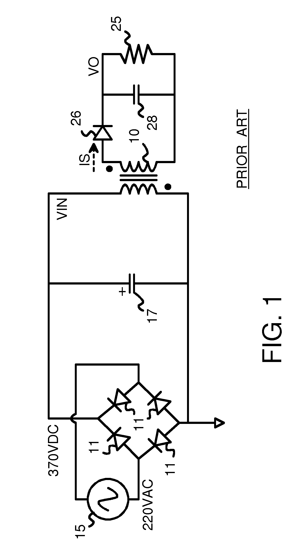
However, when large currents are used to drive loads such as LED's, this capacitor must be very large.
However, having a large capacitor on the primary side may reduce the power factor, since the primary-side rectified AC waveform is distorted and not similar to the input voltage to the diode bridge.
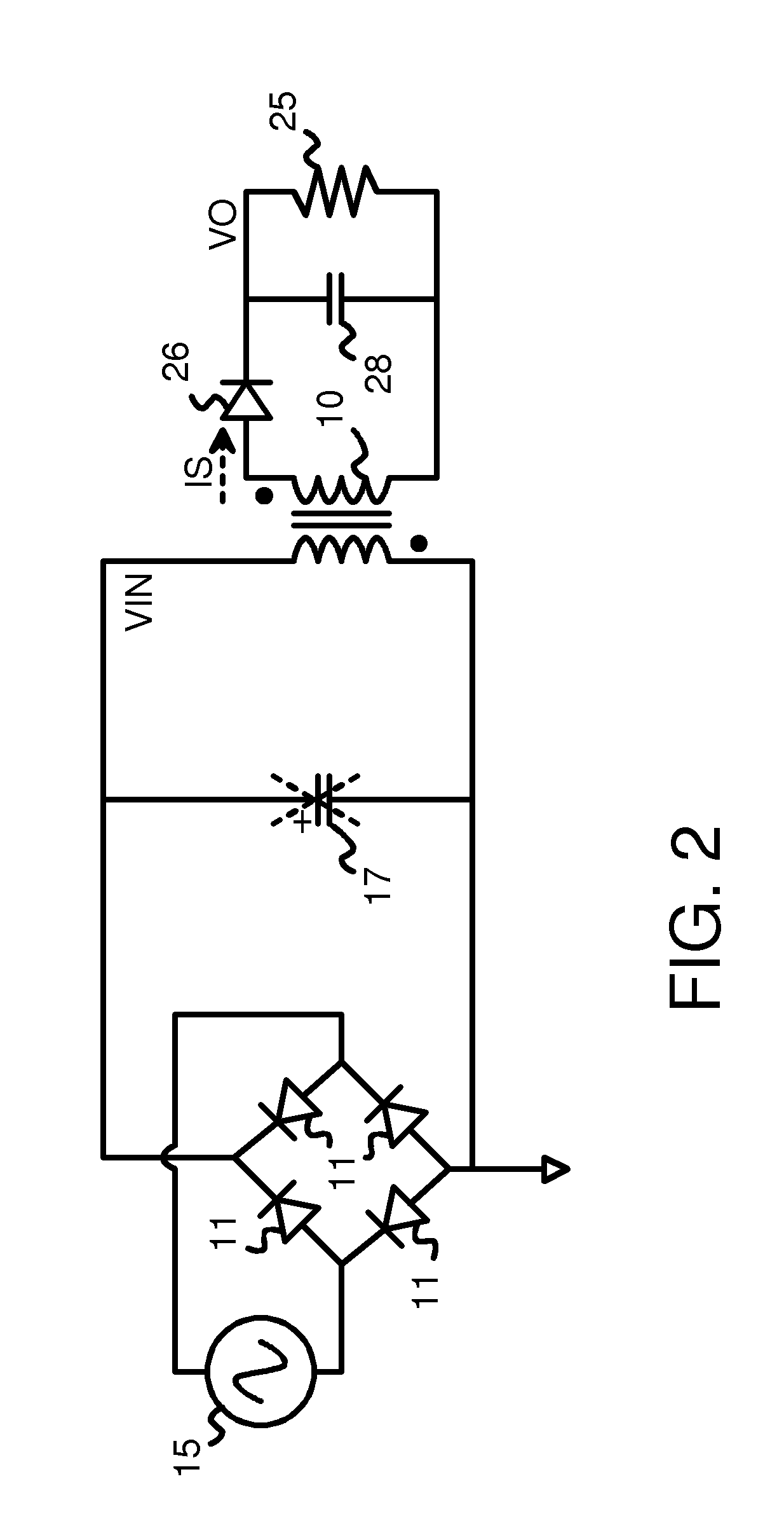
However, these high-voltage electrolytic capacitors are prone to failure.
A short or leakage in the high-voltage electrolytic capacitor used to reduce ripple may cause the LED driver circuit to fail, reducing the rated lifetime of the LED lighting product.
Although the LED itself has a high lifetime, the high-voltage electrolytic capacitor on the primary side of the LED driver circuit may reduce the lifetime of the overall LED lighting product.
High voltage electrolytic capacitors are bulky compared with low voltage capacitors.
These high-voltage electrolytic capacitors are not only expensive, but also failure prone.
Leakage in the high-voltage electrolytic capacitors can limit the rated lifetime of the overall LED circuit.
However, the opto-coupler may degrade over time, such as by dirt accumulation that blocks light.

Method used


Image

  • LED Driver with Small Output Ripple Without Requiring a High-Voltage Primary-Side Electrolytic Capacitor
  • LED Driver with Small Output Ripple Without Requiring a High-Voltage Primary-Side Electrolytic Capacitor
  • LED Driver with Small Output Ripple Without Requiring a High-Voltage Primary-Side Electrolytic Capacitor

Examples


Embodiment Construction

[0019]The present invention relates to an improvement in power drivers. The following description is presented to enable one of ordinary skill in the art to make and use the invention as provided in the context of a particular application and its requirements. Various modifications to the preferred embodiment will be apparent to those with skill in the art, and the general principles defined herein may be applied to other embodiments. Therefore, the present invention is not intended to be limited to the particular embodiments shown and described, but is to be accorded the widest scope consistent with the principles and novel features herein disclosed.

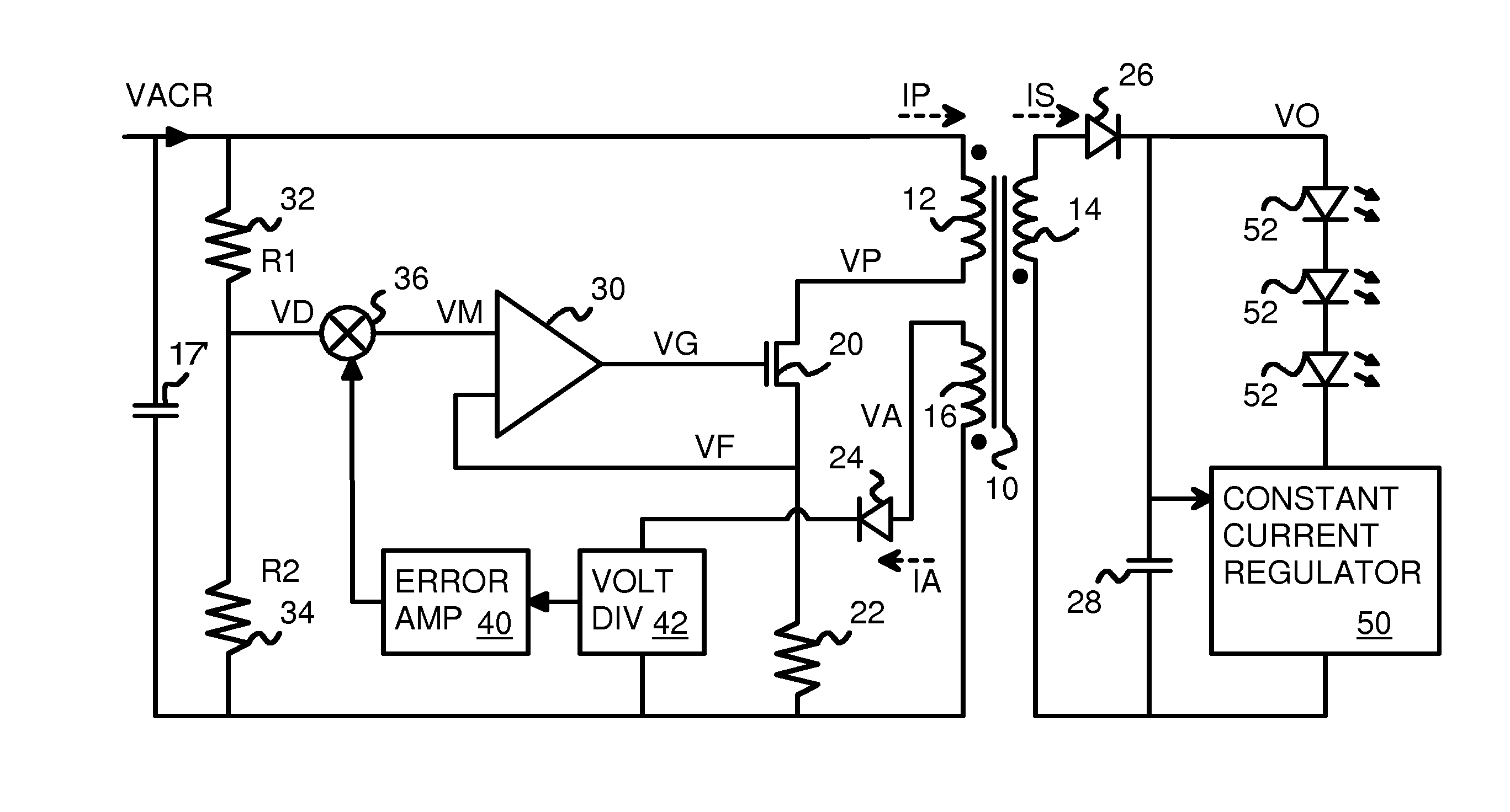
[0020]FIG. 3 shows a diagram of a power converter that switches the primary current. An AC supply produces an alternating-current that is applied to a full-wave rectifier bridge of diodes (not shown) to generate a rectified AC input voltage VACR.

[0021]Transformer 10 can have an iron core to enhanced mutual inductance between primary win...


PUM


Abstract

A power converter reduces output ripple without using an electrolytic primary-side capacitor that can reduce product lifetime. Primary-Side Regulation (PSR) using an auxiliary winding provides a regulated secondary voltage with some low-frequency ripple on a secondary winding of a transformer. A smaller secondary capacitor that is not an electrolytic capacitor filters the output of the secondary side. A bang-bang controller controls the secondary side current to reduce current ripple despite voltage ripple. The bang-bang controller has a series resistor and inductor in series with a load such as an LED. A voltage drop across the series resistor increases when a switch turns on. This increasing voltage drop toggles the switch off once an upper limit voltage is reached. The voltage drop then decreases as inductor current is shunted by a diode, until the voltage drop reaches a lower limit voltage and the switch toggles on again.

Description

FIELD OF THE INVENTION[0001]This invention relates to high-power driver circuits, and more particularly to reduced output-current ripple using a bang-bang controller.BACKGROUND OF THE INVENTION[0002]A high current is required for certain applications. Energy conservation has increased the demand for Light-Emitting Diode (LED) lighting to replace traditional lamps. A very high current such as half of an amp may need to be driven through one or more LED's to provide the desired luminosity. The power source may be an Alternating-Current (A.C.) source such as provided by an electric utility or portable generator or alternator on a moving vehicle.[0003]A rectifier such as a full diode bridge and a transformer may be used to convert power and drive the LED or other load. A residual of the A.C. input may appear on the output as a variation or ripple that may match the A.C. frequency, such as 120 or 100 Hz. This ripple may be reduced by using a capacitor across the diode bridge. However, wh...

Claims


Application Information

Patent Timeline
Patent Type & Authority Applications(United States)
IPC IPC(8): H02M3/335H02M1/42H05B33/08H05B44/00
CPCH02M3/33507H05B33/0815H02M1/42Y02B70/126H02M1/15H02M1/4258Y02B70/10H05B45/385
Inventor CHANG, PO WAHNG, CHIK WAI (DAVID)KWAN, HING KITSO, WAI KIT (VICTOR)WU, SHAOBINKWONG, KWOK KUEN (DAVID)
Owner HONG KONG APPLIED SCI & TECH RES INST
Learn More