
Display apparatus, display module and pixel structure thereof

a display module and display apparatus technology, applied in the field of display technology, can solve the problems of high resolution requirement, inability to install both the display unit and the flexible circuit board, and inability to achieve optical symmetry and uniformity, and achieve the effect of high resolution requiremen

Active Publication Date: 2015-12-24
E INK HLDG INC
View PDF10 Cites 3 Cited by
  • Summary
  • Abstract
  • Description
  • Claims
  • Application Information

AI Technical Summary

Benefits of technology

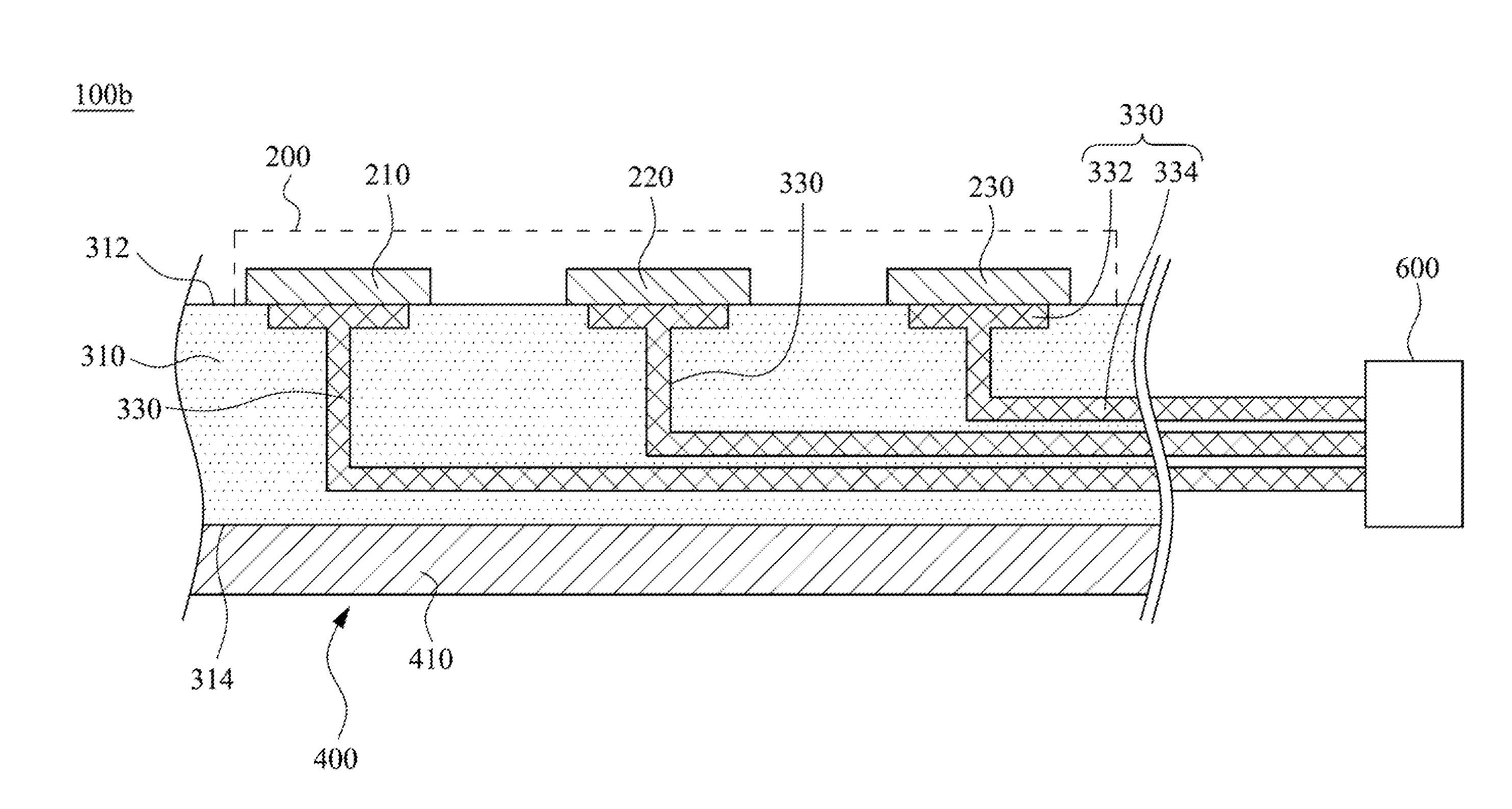
The present invention improves the resolution of an LED display apparatus by balancing high resolution requirements and optical symmetry and uniformity. This is achieved by reducing the intervals between the display units while keeping them equal. The pixel structure is designed to have LED chips mounted on a flexible circuit board, which reduces the area of the pixel structure and the size of the display apparatus.

Problems solved by technology

As such, the display unit and the space reserving for the flexible circuit board overlap, which causes the installation of both the display unit and the flexible circuit board impossible.
As a result, how to balance high resolution requirement and the optical symmetry and uniformity is a dilemma in the development of the LED display.

Method used


Image

  • Display apparatus, display module and pixel structure thereof
  • Display apparatus, display module and pixel structure thereof
  • Display apparatus, display module and pixel structure thereof

Examples


Embodiment Construction

[0021]Reference will now be made in detail to the present embodiments of the invention, examples of which are illustrated in the accompanying drawings. Wherever possible, the same reference numbers are used in the drawings and the description to refer to the same or like parts.

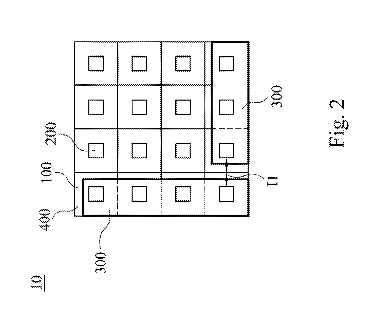
[0022]FIG. 1 is a schematic top view of a display apparatus 1 in accordance with one embodiment of the present invention. As shown in FIG. 1, in this embodiment, the display apparatus 1 includes a plurality of display modules 10 joined to each other. The number of the display modules 10 can be chosen based on the size requirement of the display apparatus 1. It is noted that the term “joined” in this context means that the edges of two display modules 10 adjacent to each other are in contact to each other and are secured. FIG. 2 is a schematic top view of the display module 10 in accordance with one embodiment of the present invention. As shown in FIG. 2, the display module 10 includes a plurality of pixel stru...


PUM


Abstract

A pixel structure located on a periphery of a display module includes a substrate, a flexible circuit board and a plurality of LED chips. The substrate has at least one scribing tolerance reserving zone and a display unit mounting zone. The flexible circuit board is disposed on the display unit mounting zone of the substrate. The LED chips are mounted on the flexible circuit board.

Description

RELATED APPLICATIONS[0001]This application claims the priority benefit of provisional application Ser. No. 62 / 014,679, filed Jun. 19, 2014, the full disclosure of which is incorporated herein by reference. This application also claims the priority benefit of Taiwanese application serial no. 103143872, filed Dec. 16, 2014, the full disclosure of which is incorporated herein by reference.BACKGROUND[0002]1. Technical Field[0003]The present invention relates to a display technology, and more particularly, to a display apparatus, a display module and a pixel structure thereof.[0004]2. Description of Related Art[0005]In pace with the rapid development of the display technology, flat panel displays other than the typical LCD have employed the light emitting diode (LED) as pixel to directly show images. Because the LED itself has advantages such as high brightness, high contrast ratio, low driving voltage, high activation speed, high lighting efficiency, and high stability, the LED display ...

Claims


Application Information

Patent Timeline
Patent Type & Authority Applications(United States)
IPC IPC(8): H01L25/16H01L23/538H01L27/12G09G3/32
CPCH05K2201/10106H05K2201/10128H05K1/113H05K1/189G09G3/3216G09G3/3225G09G2300/026G09G2300/06G09G3/32H01L27/1214G09G2300/0426G09G2300/08G09G2300/0465G09F9/3026H01L2924/0002H01L2924/00
Inventor CHANG, YUNG-SHENGYEH, CHIA-CHUN
Owner E INK HLDG INC
Learn More