
Film mirror for solar radiation collection and method for producing same

a technology of solar radiation and film mirror, which is applied in the safety of solar heat collectors, lighting and heating equipment, instruments, etc., can solve the problems of not reaching the level presently required in lightfastness, and achieve excellent adhesion of protective layers and excellent lightfastness

Inactive Publication Date: 2015-12-24
FUJIFILM CORP
View PDF2 Cites 8 Cited by
  • Summary
  • Abstract
  • Description
  • Claims
  • Application Information

AI Technical Summary

Benefits of technology

The present invention solves the problem of poor adhesion and lightfastness of film mirrors used for solar radiation collection. This is achieved by adding a prescribed amount of corrosion inhibitor to the surface of the reflective layer. A film mirror with excellent adhesion and lightfastness can thus be provided.

Problems solved by technology

Furthermore, when they decreased the amount of corrosion inhibitor used in order to promote curing, lightfastness did not reach the level presently required, and further improvement was necessary.

Method used


Image

  • Film mirror for solar radiation collection and method for producing same
  • Film mirror for solar radiation collection and method for producing same
  • Film mirror for solar radiation collection and method for producing same

Examples


first embodiment

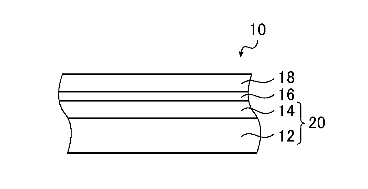
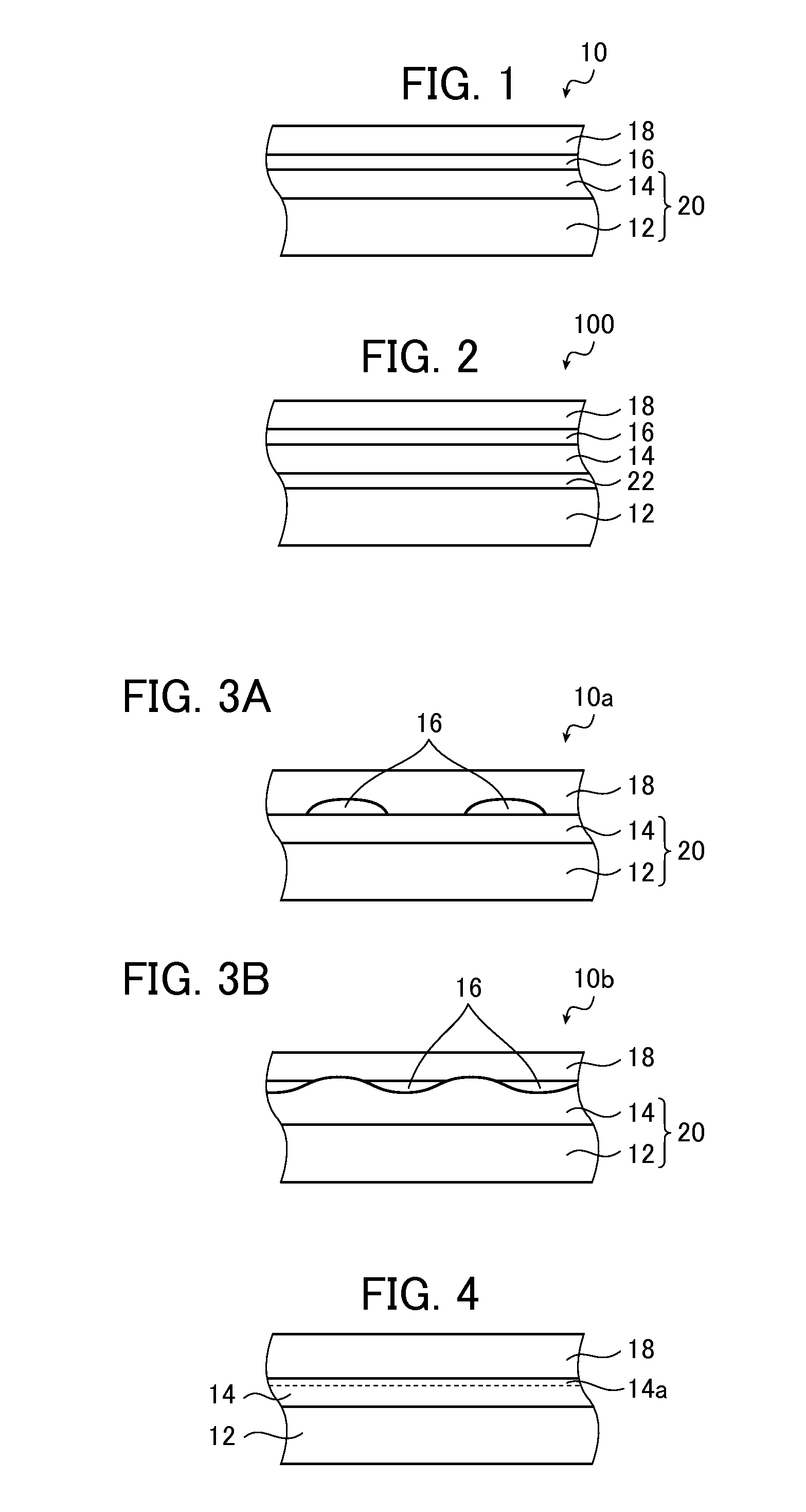
[0031]A first embodiment of the film mirror for solar radiation collection (hereafter also referred to simply as “film mirror”) of the present invention will be described in reference to the drawings. FIG. 1 is a section view illustrating an embodiment of the film mirror of the present invention.

[0032]A film mirror 10 has a resin substrate 12, a silver reflective layer 14, a corrosion inhibitor 16, and a protective layer 18 in this order. Light such as solar radiation is incident from the protective layer 18 side, and is reflected on the surface of the silver reflective layer 14. Furthermore, the resin substrate 12 and the silver reflective layer 14 constitute a resin substrate-silver reflective layer combination 20.

[0033]Each of the layers that constitute the film mirror 10 will be described in detail below.

[Resin Substrate]

[0034]The resin substrate 12 is a substrate that imparts flexibility to the film mirror 10. The type of the substrate is not particularly limited provided that ...

second embodiment

[0130]A second embodiment of the film mirror of the present invention is described below in reference to the relevant drawing. FIG. 2 is a section view of the second embodiment of the film mirror of the present invention.

[0131]A film mirror 100 has a resin substrate 12, a primer layer 22, a silver reflective layer 14, a corrosion inhibitor 16, and a protective layer 18 in this order.

[0132]The film mirror 100 illustrated in FIG. 2 has the same configuration as that of the film mirror 10 illustrated in FIG. 1 except that it has the primer layer 22; therefore, the same reference signs are given to the same constituent elements, and descriptions thereof are omitted, and the primer layer 22 is primarily described in detail below.

[Primer Layer]

[0133]The primer layer 22 is disposed between the resin substrate 12 and the silver reflective layer 14, and increases the adhesion between the two.

[0134]The primer layer 22 is obtained by performing heat treatment and / or photoirradiation on a layer...

examples

[0193]The present invention will be described in further detail in reference to the following Examples, to which the present invention is not limited.


PUM

PropertyMeasurementUnit
thicknessaaaaaaaaaa
thicknessaaaaaaaaaa
thicknessaaaaaaaaaa

Abstract

A film mirror for solar radiation collection includes at least a protective layer, a silver reflective layer and a resin substrate in this order from a light incident side and has a corrosion inhibitor present at either or both of a surface and a surface layer of the silver reflective layer on the protective layer side, with the content of the corrosion inhibitor being 0.1 to 10 mg / m2. The film mirror for solar radiation collection is excellent in adhesion of the protective layer and in lightfastness as well.

Description

CROSS-REFERENCE TO RELATED APPLICATIONS[0001]This application is a continuation of PCT International Application No. PCT / JP2014 / 051985 filed on Jan. 29, 2014, which was published under PCT Article 21(2) in Japanese, which claims priority under 35 U.S.C. §119(a) to Japanese Patent Application No. 2013-031243 filed on Feb. 20, 2013, Japanese Patent Application No. 2013-191808 filed on Sep. 17, 2013, and Japanese Patent Application No. 2013-263673 filed on Dec. 20, 2013. The above applications are hereby expressly incorporated by reference, in their entirety, into the present application.BACKGROUND OF THE INVENTION[0002]The present invention relates to a film mirror for solar radiation collection and a method for producing the same, and particularly relates to a film mirror for solar radiation collection having a prescribed amount of a corrosion inhibitor on a surface and / or in a surface layer of a silver reflective layer, and a method for producing such a film mirror.[0003]Glass mirro...

Claims


Application Information

Patent Timeline
Patent Type & Authority Applications(United States)
IPC IPC(8): G02B5/08F24S23/70
CPCG02B5/085Y10T29/49828G02B5/0891B32B15/08B32B2307/416B32B2307/71B32B2307/714B32B2551/08F24S23/82F24S40/40G02B5/0808G02B1/14Y02E10/40
Inventor TOMINAGA, JOUISOBE, HIDEMIAONO, NARUHIKO
Owner FUJIFILM CORP
Learn More