
Electric Bike Retrofit for Disc Brakes Bicycle

a technology of disc brakes and bicycles, applied in the field of bicycles, can solve the problems of electric bicycles, impose a significant financial burden on many consumers, and are considerably expensiv

Inactive Publication Date: 2015-12-24
SECURIENCE
View PDF0 Cites 14 Cited by
  • Summary
  • Abstract
  • Description
  • Claims
  • Application Information

AI Technical Summary

Benefits of technology

The patent describes a retrofit assembly for a bicycle that includes an electric motor and brake rotor. The electric motor is attachable to the bicycle frame and can be engaged with the brake rotor to provide rotational force to the bicycle. The assembly can be easily attached without modifying the brake caliper, frame, or wheels. The brake rotor may have gear teeth that selectively engage with a motor gear, and the motor gear may be engageable with multiple rings on the brake rotor to provide different gear ratios. The electric motor can also provide regenerative braking and can be attached to the brake caliper or rear wheel axle. The invention allows for the easy addition of electric power to a bicycle without making major modifications.

Problems solved by technology

One drawback to electric bicycles is that they are considerably expensive.
When the bicycle is designed from the ground up to incorporate electronic controls, an electric, motor, a battery pack, and the necessary hardware, it imposes a significant financial burden that many consumers are not willing to absorb, As a result, retrofitting existing bicycles with electric drives has become popular.
One problem is that there is limited space available on a bicycle frame to accommodate the electric drive equipment.
Another drawback to existing electric drive retrofits is that they utilize their own components to transfer the assisted power from the electric motor to the bicycle.
This solution is typically very expensive and wheel damage is harder to repair as it is not a common “off the shelf” item.
An added chain or belt is then used, providing additional weight, complexity, and maintenance to the bicycle.

Method used


Image

  • Electric Bike Retrofit for Disc Brakes Bicycle
  • Electric Bike Retrofit for Disc Brakes Bicycle
  • Electric Bike Retrofit for Disc Brakes Bicycle

Examples


Embodiment Construction

[0021]The present invention and the various features and advantageous details thereof are explained more fully with reference to the non-limiting embodiments described in detail in the following description. While the invention is directed toward use with bicycles, it is not limited to just traditional bicycles. The term “bicycle” is used to include any multi-wheeled form of transportation which may or may not include a seat. For example, scooters that support a rider in an upright, standing position are also included in the term “bicycle”. The “bicycle” may be chain driven, belt driven, pulley driven, gear driven, or any other form of rotational motion delivery.

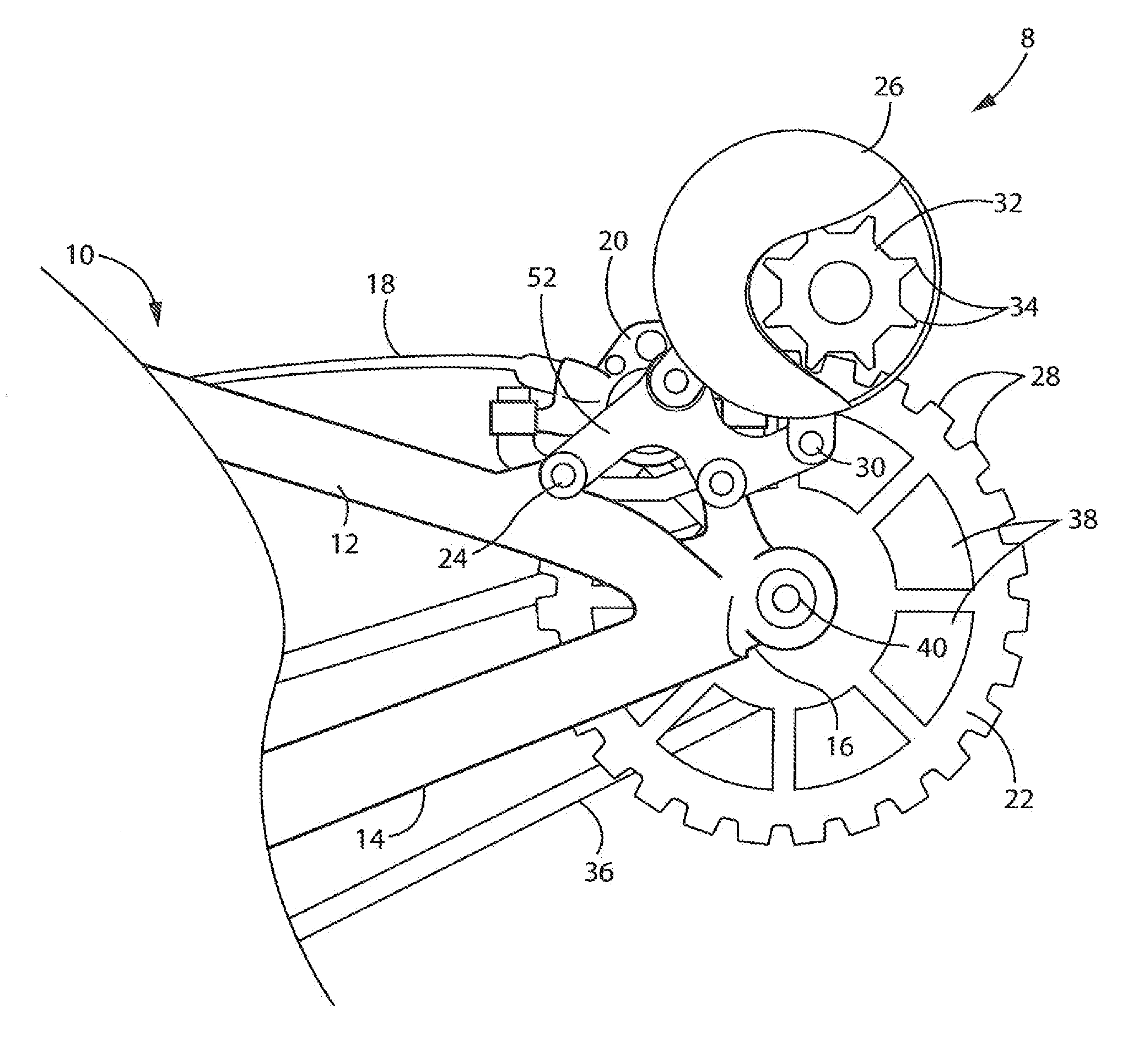
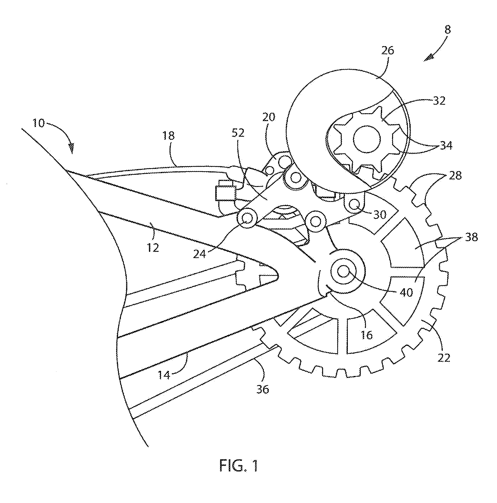
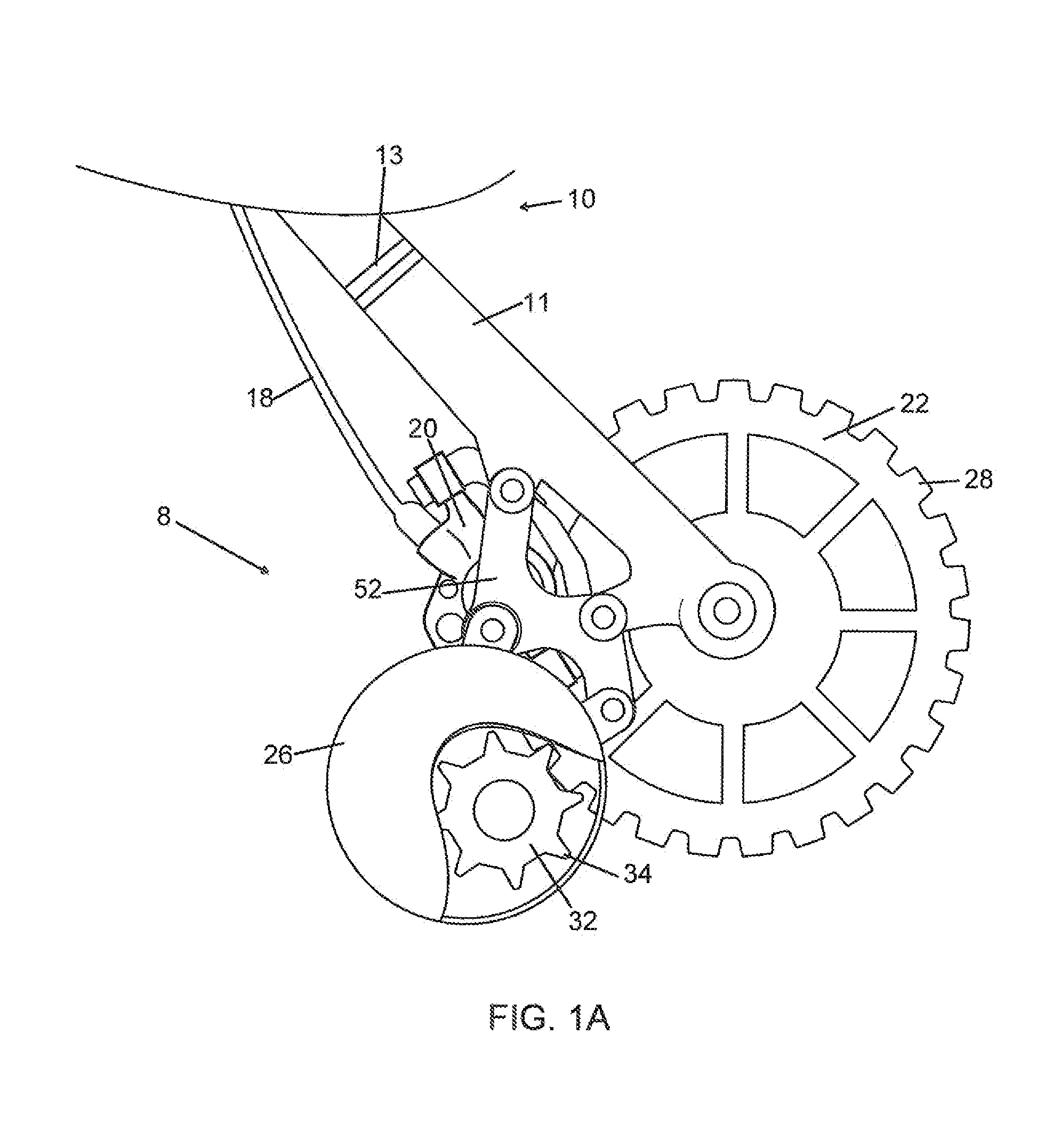
[0022]An electric drive 8 retrofit is shown in FIG. 1 attached to a frame 10 of a bicycle. Bicycle frames 10 commonly include a seat stay tube 12 and a chain stay tube 14 that converge at a rear wheel dropout 16. The electric drive may also attach to any other bicycle regardless of the frame design. While it is preferred tha...


PUM


Abstract

An apparatus and method for an electric bike retrofit for disc brakes vehicle include an electric motor coupled with a rotor brake. The apparatus and method provide advantages in that the drive gear for the electric motor may be integrated with the brake rotor decreasing weight and minimizing necessary parts. The electric motor may mount to the existing brake caliper mounts and drive the brake rotor without the use of a chain, belt, or the like. Multiple gear ratios may be incorporated into the brake rotor allowing for shifting and increased efficiency of the electric drive system.

Description

BACKGROUND OF THE INVENTION[0001]1. Field of the Invention[0002]The present invention relates in general to the field of electrical assist of traditionally human powered vehicles, e.g., bicycles, scooters, etc. More particularly, the present invention relates to bicycles equipped with a braking system that utilizes brake rotors and calipers. Specifically, the present invention relates to retrofitting electric assist to pedal-powered bicycles that use brake rotors and calipers.[0003]2. Discussion of the Related Art[0004]Riding bicycles is a popular pastime for physical exercise as well as a means of transportation. In an effort to promote the utilitarian benefits of bicycle riding, electric bicycles have become popular in recent times. Electric bicycles allow individuals to use the same bicycle to get physical exercise as well as a means of transportation while avoiding exhaustion. This may be done by allowing the operator to pedal as the sole means of propulsion, use an electric dri...

Claims


Application Information

Patent Timeline
IPC IPC(8): F16D65/16B62L3/00
CPCF16D65/16B62L3/00F16D2125/48F16D2125/52F16D2121/24F16D65/123F16D2065/1332B62M6/60
Inventor MUEHLBAUER, DON J.
Owner SECURIENCE
Learn More