
Apparatus and method embedding a camera in an LED streetlight

a technology of led streetlights and cameras, applied in the direction of lighting support devices, television systems, instruments, etc., can solve the problems of improper exposure of video/pictures, overheating of camera and light components,

Inactive Publication Date: 2015-12-17
CLAIRVOYANCE LLC
View PDF5 Cites 73 Cited by
  • Summary
  • Abstract
  • Description
  • Claims
  • Application Information

AI Technical Summary

Benefits of technology

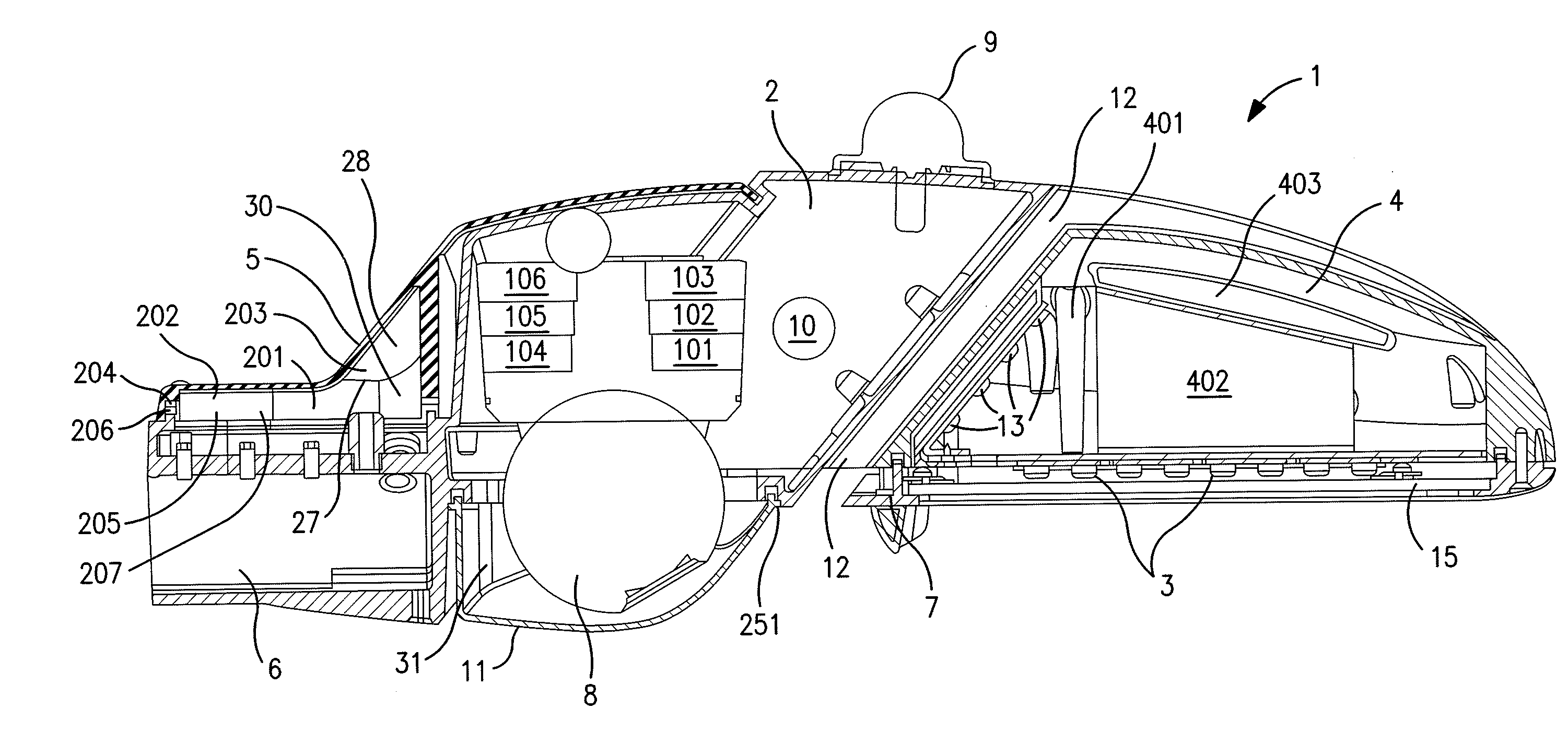
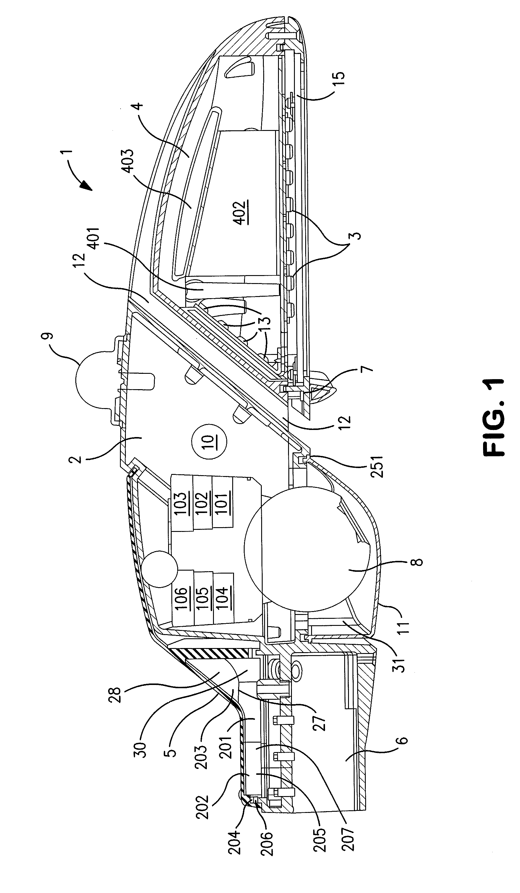
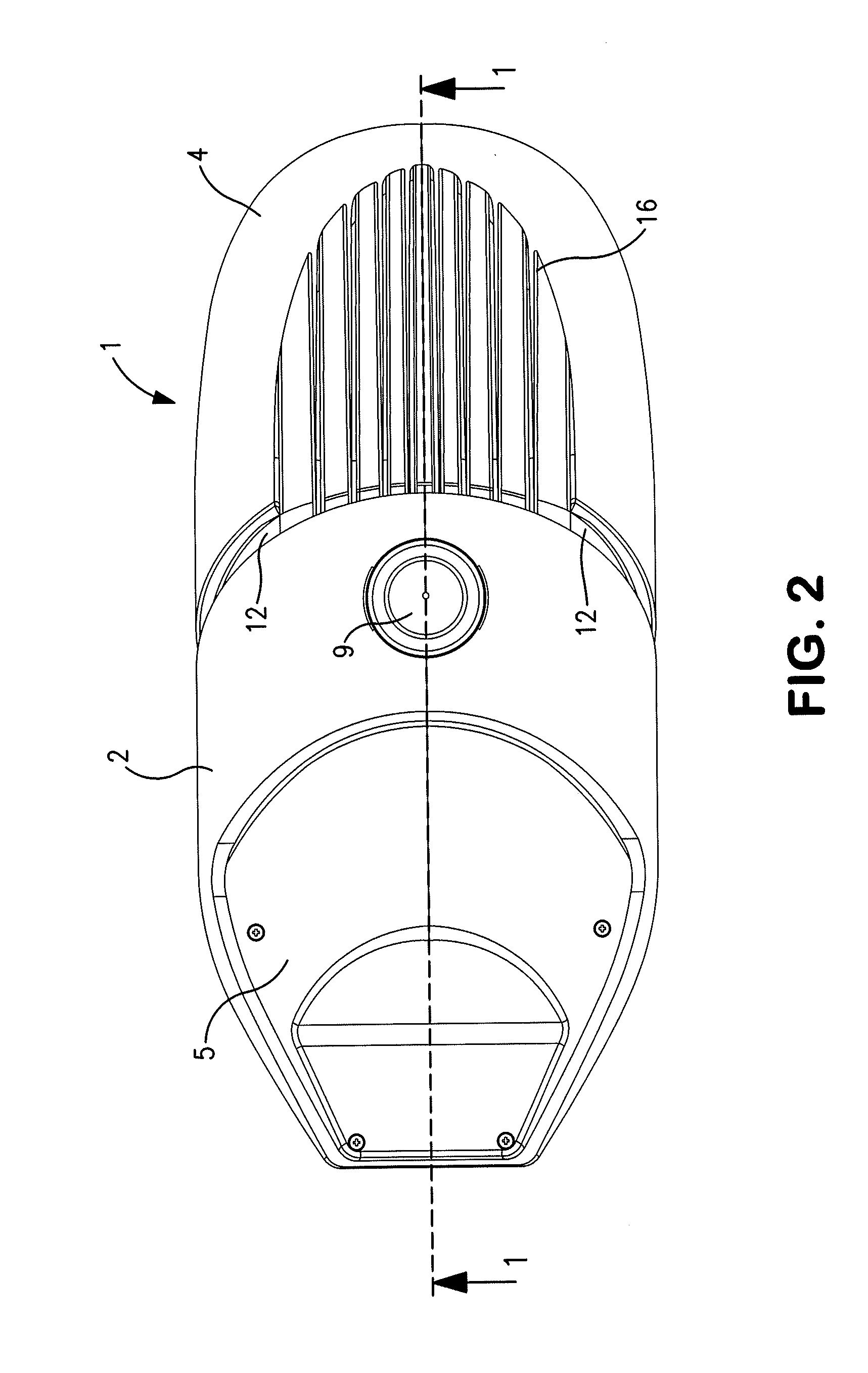
This patent is about an apparatus and method of embedding a camera in a street light. The invention has a unique structure that allows for illuminating an area beneath the street light with an LED array while capturing images of the area with a camera in a separate compartment. The camera is shielded from light glare and reflections from the LED array and is cooled using a passive cooling air channel. The invention also provides a power supply compartment for the LED light array and a support structure for the enclosure housing the apparatus. The technical effects of the invention include improved monitoring and surveillance capabilities, as well as an improved aesthetic appearance on the street.

Problems solved by technology

Even with the fan, overheating of the camera and light components is a problem.
Beside the overheating problems engendered by such a design, the light from the lamp bulbs will likely enter onto the camera module, resulting in improperly-exposed video / pictures.

Method used


Image

  • Apparatus and method embedding a camera in an LED streetlight
  • Apparatus and method embedding a camera in an LED streetlight
  • Apparatus and method embedding a camera in an LED streetlight

Examples


Embodiment Construction

1. Introduction

[0019]The presently preferred exemplary embodiments provide a unique combination of features whereby a fixed and / or PTZ camera is mounted in a street light enclosure, in a compartment separate from the LED light compartment. With this design, heat-generation is properly managed, and the lighting functions will not interfere with the camera functions. Preferably, the fixed and / or PTZ camera lens is mounted beside but vertically below the LED compartment to prevent light pollution to the camera. As a further aid in lighting control, an anti-glare spoiler may be mounted between the light compartment and the camera compartment, to shield the camera from the light. To properly manage the generated heat, the heat-generating components of the LED lights are preferably located remotely from the LED compartment. Additionally, a passive-cooling air channel is preferably disposed between the camera compartment and the LED compartment, sloping upward from the bottom of the street...


PUM


Abstract

Apparatus and method embedding a camera in a street light includes structure and / or function whereby the street light, comprising has a first compartment having an LED array configured to illuminate an area beneath the street light. A second compartment is coupled to the first compartment and has a camera directed toward the area beneath the street light. The second compartment has a window covering the camera such that the camera can receive light from area beneath the street light, but passers-by do not see the camera. A third compartment is coupled to the second compartment and is configured to attach the street light to a vertical support. A passive air channel is disposed between the first compartment and the second compartment, and is configured to direct air from beneath the street light to the top of the street light. Preferably, the power supply for the LED array is disposed in a compartment different that the first compartment. An anti-glare device is preferably mounted to a bottom of at least one of the first compartment and the second compartment, and is configured to shield the camera from light glare and / or reflections from the LED array.

Description

BACKGROUND OF THE INVENTION[0001]1. Field of the Invention[0002]The present invention relates to apparatus and method whereby a camera mounted in an LED streetlight is enabled to monitor a field of view and report what is observed. In a preferred embodiment, a fixed camera and / or a Pan-Tilt-Zoom (PTZ) camera is used, and it is remotely controlled by, and communicates image(s) and / or reports to, a remote control center via one or more of wireless (e.g., WiFi, WiMax, GSM, Bluetooth, satellite, etc.) and / or land-line (e.g., coaxial cable, Ethernet, fiber optics, etc.) modalities. Preferably, the camera is not visible from the area monitored.[0003]2. Background Art[0004]Street lights are found all over the world. They are used to light public roads, paths, and areas during night time, and to provide safety to the citizens and visitors of such areas. Cameras may be installed in such street lights to view the areas below the streetlight, thus providing security to the public and providing...

Claims


Application Information

Patent Timeline
IPC IPC(8): F21V33/00F21V11/16H04N5/225F21V29/83H04N7/18F21S8/08F21V23/02
CPCF21V33/0052F21S8/088F21V11/16F21Y2101/02F21V29/83H04N7/183H04N5/2252F21V23/023F21S8/086F21V21/116F21V23/0435G08B13/19632G08B15/001F21W2131/103G08B13/1966F21Y2105/10F21Y2115/10G08B25/10F21S8/085H04N23/51
Inventor GABRIEL, WILFRIEDEBERL, GERHARD
Owner CLAIRVOYANCE LLC
Learn More