
Vehicle visor vanity light and actuator assembly

Inactive Publication Date: 2015-12-17
INNOTEC CORP
View PDF13 Cites 15 Cited by
  • Summary
  • Abstract
  • Description
  • Claims
  • Application Information

AI Technical Summary

Benefits of technology

The present invention is a lighting assembly that has several benefits. First, it reduces the cost by using fewer light sources and related equipment. Second, it ensures consistent color harmony across multiple light sources or locations. Third, it requires less physical space, making it possible to make the visor or other supporting component thinner or smaller.

Problems solved by technology

Third, the assembly requires a smaller physical space, enabling the visor or other supporting component to be thinner or otherwise smaller.

Method used


Image

  • Vehicle visor vanity light and actuator assembly
  • Vehicle visor vanity light and actuator assembly
  • Vehicle visor vanity light and actuator assembly

Examples


Embodiment Construction

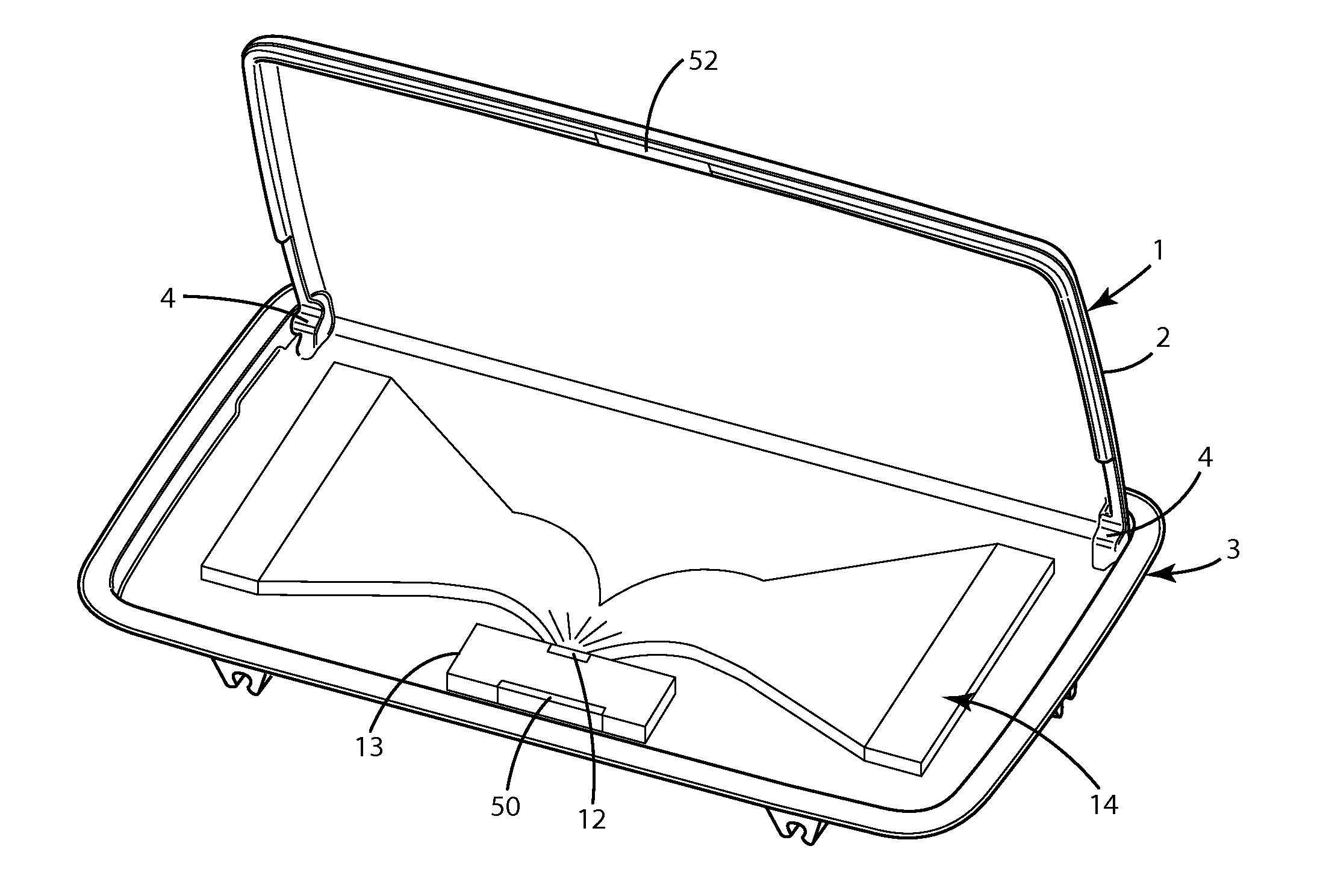
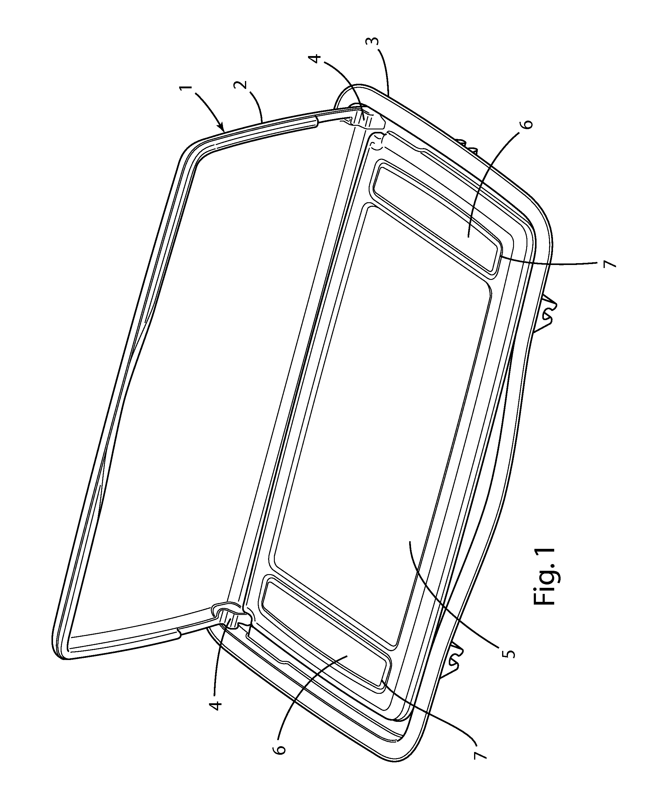
[0031]With reference to FIG. 1, a lighted accessory according to one aspect of the present invention comprises a vehicle sun visor vanity 1. The visor vanity 1 includes a movable cover 2 that is hingedly connected to a housing or support structure 3 by hinges 4 in a known manner. The support structure 3 may include a mirror 5 for use by a vehicle occupant. The cover 2 and the support structure 3 may comprise molded polymer or any other suitable material. A pair of diffusers 6 of a light pipe or light distribution member 14 (FIG. 2) are disposed within openings 7 of the support structure 3 adjacent or proximate the opposite ends of the minor 5.

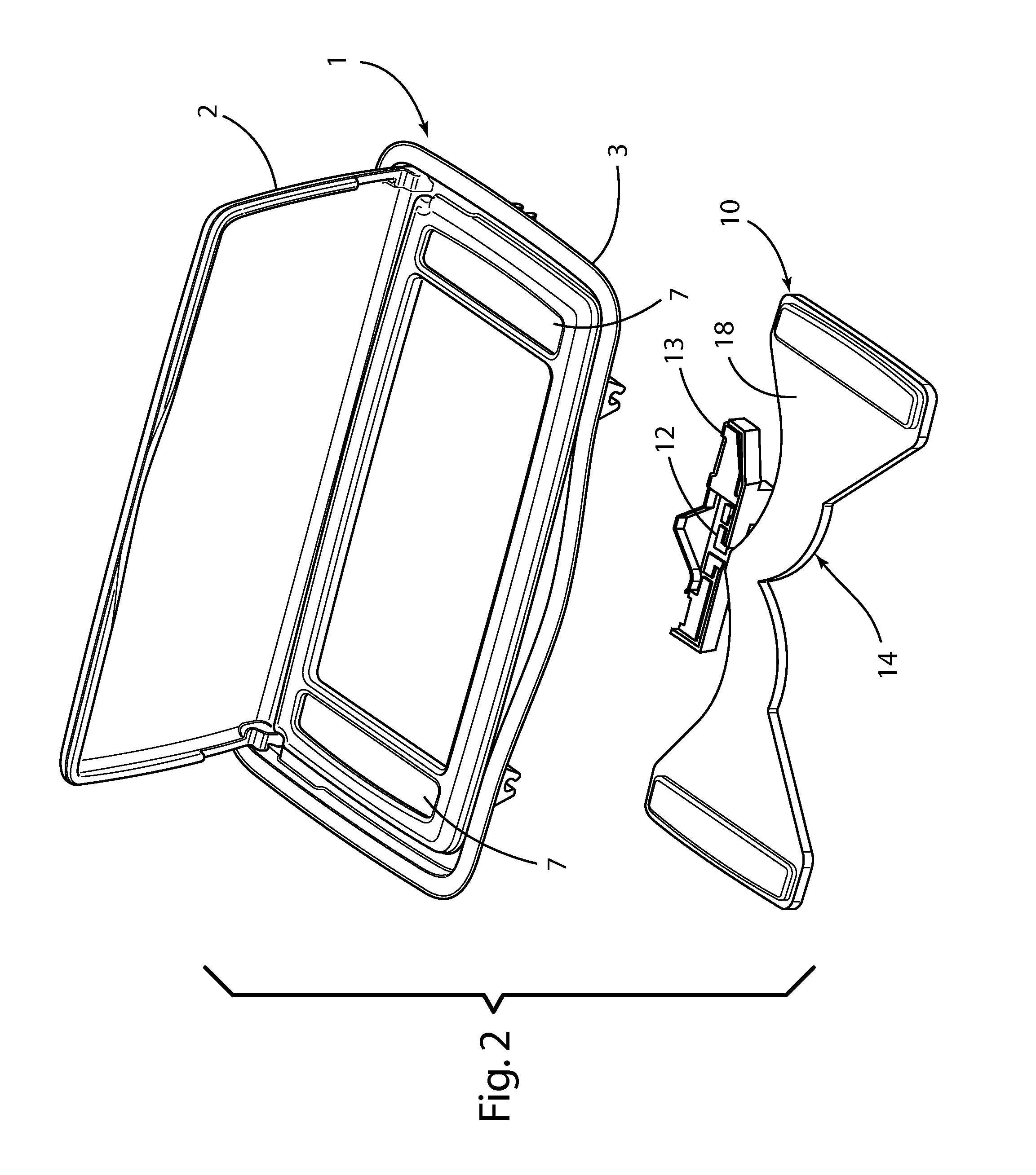
[0032]With further reference to FIG. 2, a light assembly 10 of or for the visor vanity 1 includes a light source 12 and a light guide or light pipe 14 that conveys light from the light source 12 to the diffusers 6. The light pipe 14 may be a single piece or multiple pieces. The diffusers 6 may be integral with the light pipe 14.

[0033]The light ...


PUM


Abstract

The specification discloses a vehicle visor including a vanity light assembly and an actuator assembly. The visor vanity additionally includes a mirror and a movable mirror cover. The light assembly includes a light source and a light pipe for conveying light from the light source to two or more diffusers, for example, on opposite ends of the mirror. The actuator assembly includes a switching arrangement for switching the light source on and off without flicker or noise in response to the opening and closing of the mirror cover.

Description

BACKGROUND OF THE INVENTION[0001]The present invention relates to lighting, and more particularly to vanity lighting for vehicle visors.[0002]Various types of vehicle visor vanity lighting have been developed. Typically, the visor includes a mirror, and the lighting may be configured to illuminate the space in front of the mirror to illuminate, for example, the face of a person using the mirror. Typically, the lighting includes lights at opposite ends of the mirror.[0003]Lighted visor vanity arrangements may suffer from various drawbacks. First, the lighting assemblies are relatively expensive. Second, the multiple lights on a single visor vanity may vary in color and intensity, creating both aesthetic and functional issues. Such variations are attributable to variations within tolerances in light sources and / or variations in the circuits powering the light sources. Third, the lighting assemblies may have undesired physical depth or thickness, requiring undesired depth or thickness ...

Claims


Application Information

Patent Timeline
IPC IPC(8): B60Q3/02B60Q3/00
CPCB60Q3/0226B60Q3/0296B60Q3/004B60Q3/82B60Q3/252B60Q3/64
Inventor LANSER, MICHAEL L.BREDEWEG, LUKE T.WEEDA, MATTHEW S.BOETSMA, JUSTIN P.DYK, STEVEN T.KRAMER, PAUL A.
Owner INNOTEC CORP
Learn More